VHDL TestBench数据产生方式
TestBench是FPGA代码编写中最重要的一个测试方式,一般情况下,只有在TestBench上测试通过了,我们才会将代码烧写到FPGA中去。TestBench的代码不像需要烧写到FPGA中的代码那么严谨,会使用一些比如wait for之类的语言。这样的代码不合乎时序规范,就会导致仿真的时候也出现一些时序问题,我们就通过一个例子来看一下。
首先这是我们要进行仿真的代码:
library IEEE;
use IEEE.STD_LOGIC_1164.ALL;
use IEEE.STD_LOGIC_ARITH.ALL;
use IEEE.STD_LOGIC_UNSIGNED.ALL;

entity camPix is
port(
  rst_n    :  IN  std_logic;
  clk      :  IN  std_logic;
  cam_da_i :  IN  std_logic_vector(7 downto 0);
  cam_da_o : OUT  std_logic_vector(3 downto 0)
  );
end camPix;

architecture Behavioral of camPix is

signal cam_da_in_dly  : std_logic_vector(7 downto 0);
signal cam_da_out_dly : std_logic_vector(3 downto 0);

begin

process(rst_n,clk)
begin
  if(rst_n = '0') then
    cam_da_in_dly <= (others => '0');
  elsif(rising_edge(clk)) then
    cam_da_in_dly <= cam_da_i;
  end if;
end process;

process(rst_n,clk)
begin
  if(rst_n = '0') then
    cam_da_out_dly <= (others => '0');
  elsif(rising_edge(clk)) then
    cam_da_out_dly <= cam_da_in_dly(5 downto 2);
  end if;
end process;

process(rst_n,clk)
begin
  if(rst_n = '0') then
    cam_da_o <= (others => '0');
  elsif(rising_edge(clk)) then
    cam_da_o <= cam_da_out_dly;
  end if;
end process;

end Behavioral;
接下来是我们的TestBench代码
library IEEE;
use IEEE.STD_LOGIC_1164.ALL;
use IEEE.STD_LOGIC_ARITH.ALL;
use IEEE.STD_LOGIC_UNSIGNED.ALL;
use STD.TEXTIO.all;
use ieee.std_logic_textio.all;
entity test_top is
end test_top;
architecture Behavioral of test_top is
COMPONENT camPix
Port(
rst_n : in std_logic;
clk : in std_logic;
cam_da_i : in std_logic_vector(7 downto 0);
cam_da_o :out std_logic_vector(3 downto 0)
);
END COMPONENT;
--------------------------------------------------------------------
constant clk_period : time := 2 ns;
--Inputs
signal rst_n : std_logic := '0';
signal cam_clk : std_logic := '0';
signal cam_da_i : std_logic_vector(7 downto 0);
signal cam_da_o : std_logic_vector(3 downto 0);
begin
-- Clock process definitions
cam_clk_process :process
begin
cam_clk <= not cam_clk;
wait for clk_period/2;
end process;
-- Reset process definitions
rst_process :process
begin
rst_n <= '0';
wait for clk_period*5;
rst_n <= '1';
wait;
end process;
-- Stimulus process
sti_process : process
begin
cam_da_i <= x"67";
wait for clk_period*5;
cam_da_i <= x"45";
wait for clk_period*3;
cam_da_i <= x"AB";
wait for clk_period*4;
end process;
CAMPIXEL : camPix
port map(
rst_n => rst_n,
clk => cam_clk,
cam_da_i => cam_da_i,
cam_da_o => cam_da_o
);
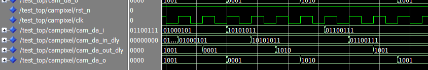
end Behavioral; 然后我们来看一下仿真的波形图

可以发现这个时序与我们想象中的有点不一样,在代码中,我们的cam_da_in_dly这个信号是比cam_da_i这个信号延时一个clk的,但是在仿真波形图中可以看到cam_da_in_dly和cam_da_i这两个信号同时变化,也就是说和我们代码中描述的不一样。
究其原因,是因为连接到campixel这个component里的cam_da_i是通过时间延时产生的,即通过wait for这种形式产生的,而并不是在process(clk)中产生的。可以这样理解,如果是在process(clk)里面产生的,那么可以认为信号与clk之间存在着因果关系,而如果是通过wait for这样的形式产生的,虽然看上去信号也像是在某个时钟上升沿产生的,但其实两者之间并不存在任何联系,或者可以理解成,wait for clk_period*5就相同于cam_da_i在(clk_period*5 -Δt)的时候产生的,所以在下一个clk触发的时候,cam_da_i_dly就被赋予了cam_da_i的值了,即在仿真波形图中看到两个信号同时发生变化。
有时候这样的时序问题不会产生什么影响,但也有不少情况下,这一个时序的错误就会导致仿真与实际情况不同,那如何解决这个问题呢。解决办法很简单,既然是因为testBench中的信号不是通过process(clk)产生而导致的,那我们就在输入到component之前先将信号延时一个clk即可。
延时一个clk之后的波形仿真图:
可以看到,现在的时序跟我们想象中的一样了。
文件操作也是TestBench里一个非常重要的部分,很多时候,我们需要通过文件来读取或者记录仿真数据,下一次更新,笔者将简单介绍一下TestBench中的文件读写操作。
