- 中斷副程式的宣告
__interrupt void cpu_timer0_isr(void);
進入副程式
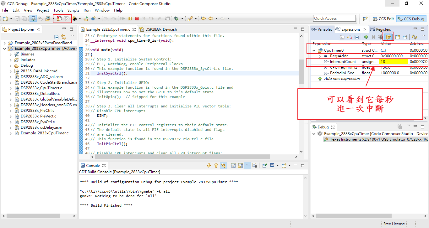
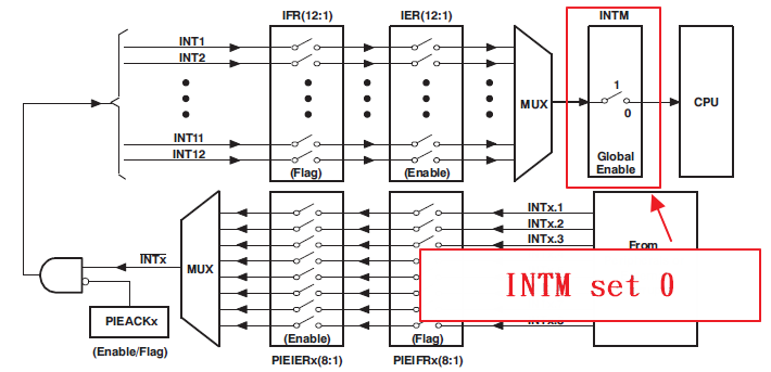
__interrupt void cpu_timer0_isr(void)
{
   CpuTimer0.InterruptCount++;

   // Acknowledge this interrupt to receive more interrupts from group 1
   PieCtrlRegs.PIEACK.all = 1;
}
其目的是把 InterruptCount ++
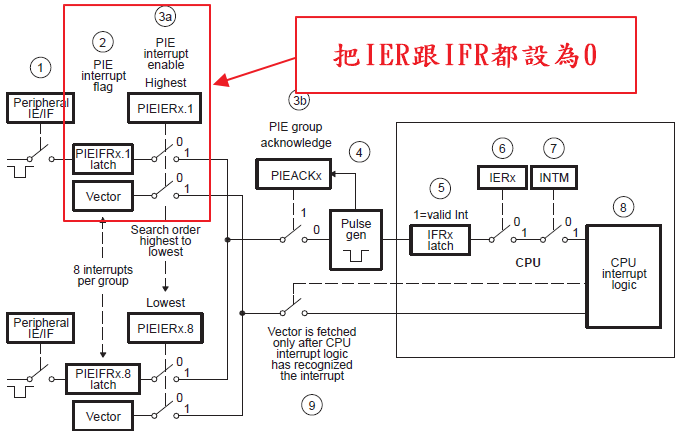
接下來 PIEACK.all = 1來把ACK信號清除(如下圖)
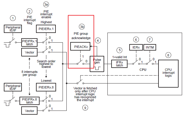
(一定要清除,不然若有其他週邊中斷就無法使用這個cpu中斷)
- 系統初始化
InitSysCtrl();
進入該程式
void
InitSysCtrl(void)
{

    DisableDog();        //Disable看門狗計數器
    InitPll(DSP28_PLLCR,DSP28_DIVSEL);     //初始SYSCLKOUT??幹!!還看不懂
    InitPeripheralClocks();
}
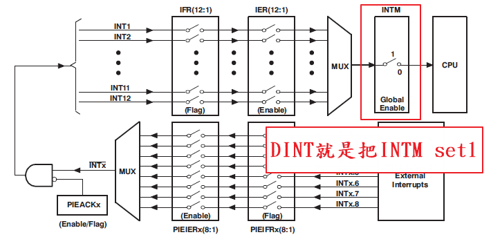
- Disable CPU interrupts
DINT; //中斷Disable
- 初始PIE的控制
InitPieCtrl();
進入該程式
void
InitPieCtrl(void)
{
    //
    // Disable Interrupts at the CPU level    DINT;


    // Disable the PIE    PieCtrlRegs.PIECTRL.bit.ENPIE = 0;

    // Clear all PIEIER registers    PieCtrlRegs.PIEIER1.all = 0;
    PieCtrlRegs.PIEIER2.all = 0;
    PieCtrlRegs.PIEIER3.all = 0;
    PieCtrlRegs.PIEIER4.all = 0;
    PieCtrlRegs.PIEIER5.all = 0;
    PieCtrlRegs.PIEIER6.all = 0;
    PieCtrlRegs.PIEIER7.all = 0;
    PieCtrlRegs.PIEIER8.all = 0;
    PieCtrlRegs.PIEIER9.all = 0;
    PieCtrlRegs.PIEIER10.all = 0;
    PieCtrlRegs.PIEIER11.all = 0;
    PieCtrlRegs.PIEIER12.all = 0;

    // Clear all PIEIFR registers

    PieCtrlRegs.PIEIFR1.all = 0;
    PieCtrlRegs.PIEIFR2.all = 0;
    PieCtrlRegs.PIEIFR3.all = 0;
    PieCtrlRegs.PIEIFR4.all = 0;
    PieCtrlRegs.PIEIFR5.all = 0;
    PieCtrlRegs.PIEIFR6.all = 0;
    PieCtrlRegs.PIEIFR7.all = 0;
    PieCtrlRegs.PIEIFR8.all = 0;
    PieCtrlRegs.PIEIFR9.all = 0;
    PieCtrlRegs.PIEIFR10.all = 0;
    PieCtrlRegs.PIEIFR11.all = 0;
    PieCtrlRegs.PIEIFR12.all = 0;
}
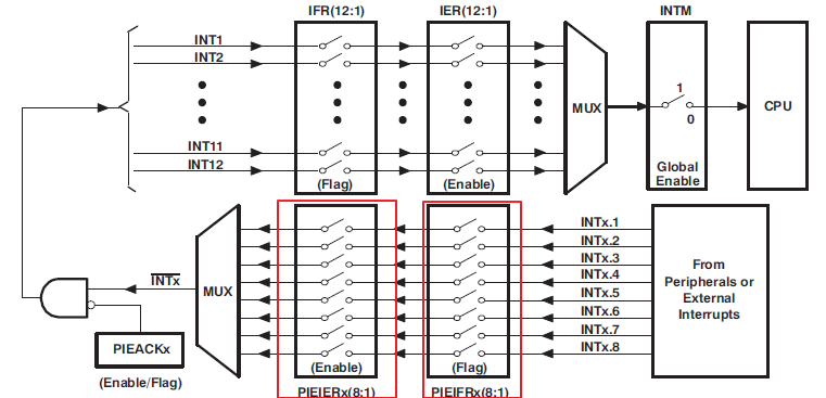
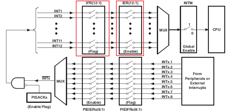
把所有的PIEIER跟PIEIFR的旗標寫成0 (如下圖參考)
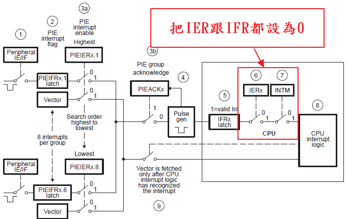
- Disable CPU interrupts and clear all CPU interrupt flags:
   IER = 0x0000;
   IFR = 0x0000;
- 初始化PIE向量表
InitPieVectTable();
- 將中斷服務程式對應到PIE中斷向量表來啟動相對應的服務
   EALLOW;  // 解除暫存器保護(有的暫存器要解開保護才能寫入)
   PieVectTable.TINT0 = &cpu_timer0_isr;
   EDIS;    // 讓暫存器進入保護
- 初始CPU Timers
InitCpuTimers();
進入
void
InitCpuTimers(void)
{
    //
    // CPU Timer 0 - 初始化地址指針到各自的定時器寄存器
    //
    CpuTimer0.RegsAddr = &CpuTimer0Regs;

    //
    // Initialize timer period to maximum(設為最大值)
    //
    CpuTimer0Regs.PRD.all  = 0xFFFFFFFF;

    //
    // Initialize pre-scale counter to divide by 1 (SYSCLKOUT)
    //
    CpuTimer0Regs.TPR.all  = 0;
    CpuTimer0Regs.TPRH.all = 0;

    //
    // 初始時,把計時器先停止  TSS=1  為停止
    //
    CpuTimer0Regs.TCR.bit.TSS = 1;

    //
    // 初始時,要重載計時器暫存器的暫存值
    //
    CpuTimer0Regs.TCR.bit.TRB = 1;

    //
    // 重置中斷計數器
    //
    CpuTimer0.InterruptCount = 0;
- 設定CPU時間
ConfigCpuTimer(&CpuTimer0, 150, 1000000); //150=>SYSCLKOUT 100000=M=10^6
進入
void
ConfigCpuTimer(struct CPUTIMER_VARS *Timer, float Freq, float Period)
{
    Uint32  temp;

    //
    // Initialize timer period
    //
    Timer->CPUFreqInMHz = Freq;
    Timer->PeriodInUSec = Period;
    temp = (long) (Freq * Period);
    Timer->RegsAddr->PRD.all = temp;    //timer period to 150MHZ  =>  設為150*10^6

    //
    // Set pre-scale counter to divide by 1 (SYSCLKOUT)  (設為一秒鐘    (為什麼是1S???還要再確認一下))
    //
    Timer->RegsAddr->TPR.all  = 0;        //除頻因子
    Timer->RegsAddr->TPRH.all  = 0;        //除頻因子 (TPRH:TPR+1=>0+1=1  故SYSCLKOUT/1=原本)

    //
    // Initialize timer control register
    //

    //
    // 1 = Stop timer, 0 = Start/Restart Timer
    //
    Timer->RegsAddr->TCR.bit.TSS = 1;     //TSS=1  Disable

    Timer->RegsAddr->TCR.bit.TRB = 1;    // 1 = reload timer  重新仔入
    Timer->RegsAddr->TCR.bit.SOFT = 1;
    Timer->RegsAddr->TCR.bit.FREE = 1;   // Timer Free Run

    //
    // 0 = Disable/ 1 = Enable Timer Interrupt   計時器中斷Enable
    //
    Timer->RegsAddr->TCR.bit.TIE = 1;

    //
    // Reset interrupt counter    (清除觀測變數)
    //
    Timer->InterruptCount = 0;
}
- 把TSS設為0來啟動Timer
CpuTimer0Regs.TCR.all = 0x4000;
(所以前面要先TSS設為1讓Timer先不跑,再把暫存器設定完成,最後再把TSS開啟)
- Enable CPU Timer 0
IER |= M_INT1;
- 啟動PIE的INT1.7
PieCtrlRegs.PIEIER1.bit.INTx7 = 1;
可對照下圖得知把中斷向量
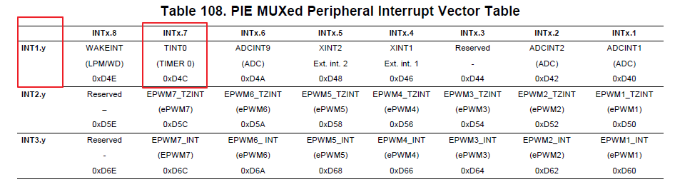
可看出INT1.7為 Timer 0 故要啟動它
- 最後步驟
// Enable global Interrupts and higher priority real-time debug events:
   EINT;   // Enable Global interrupt INTM=0
   ERTM;   // Enable Global realtime interrupt DBGM(啟動中斷在即時粉真模式下(CPU暫停)  ??靠北  也看不懂)

// Step 6. IDLE loop. Just sit and loop forever (optional):
   for(;;);
- 最後附上全部程式碼 (PS:有偷偷把Timer1&2先砍掉)
#include "DSP28x_Project.h"     // Device Headerfile and Examples Include File

// Prototype statements for functions found within this file.
__interrupt void cpu_timer0_isr(void);

void main(void)
{
// Step 1. Initialize System Control:
// PLL, WatchDog, enable Peripheral Clocks
// This example function is found in the DSP2833x_SysCtrl.c file.
   InitSysCtrl();

// Step 2. Initialize GPIO:
// This example function is found in the DSP2833x_Gpio.c file and
// illustrates how to set the GPIO to it's default state.
// InitGpio();  // Skipped for this example

// Step 3. Clear all interrupts and initialize PIE vector table:
// Disable CPU interrupts
   DINT;

// Initialize the PIE control registers to their default state.
// The default state is all PIE interrupts disabled and flags
// are cleared.
// This function is found in the DSP2833x_PieCtrl.c file.
   InitPieCtrl();

// Disable CPU interrupts and clear all CPU interrupt flags:
   IER = 0x0000;
   IFR = 0x0000;

// Initialize the PIE vector table with pointers to the shell Interrupt
// Service Routines (ISR).
// This will populate the entire table, even if the interrupt
// is not used in this example.  This is useful for debug purposes.
// The shell ISR routines are found in DSP2833x_DefaultIsr.c.
// This function is found in DSP2833x_PieVect.c.
   InitPieVectTable();

// Interrupts that are used in this example are re-mapped to
// ISR functions found within this file.
   EALLOW;  // This is needed to write to EALLOW protected registers
   PieVectTable.TINT0 = &cpu_timer0_isr;
   EDIS;    // This is needed to disable write to EALLOW protected registers

// Step 4. Initialize the Device Peripheral. This function can be
//         found in DSP2833x_CpuTimers.c
   InitCpuTimers();   // For this example, only initialize the Cpu Timers

#if (CPU_FRQ_150MHZ)
// Configure CPU-Timer 0, 1, and 2 to interrupt every second:
// 150MHz CPU Freq, 1 second Period (in uSeconds)

   ConfigCpuTimer(&CpuTimer0, 150, 1000000);
#endif

// To ensure precise timing, use write-only instructions to write to the entire register. Therefore, if any
// of the configuration bits are changed in ConfigCpuTimer and InitCpuTimers (in DSP2833x_CpuTimers.h), the
// below settings must also be updated.

   CpuTimer0Regs.TCR.all = 0x4000; // Use write-only instruction to set TSS bit = 0


// Step 5. User specific code, enable interrupts:

// Enable CPU int1 which is connected to CPU-Timer 0, CPU int13
// which is connected to CPU-Timer 1, and CPU int 14, which is connected
// to CPU-Timer 2:
   IER |= M_INT1;
   IER |= M_INT13;
   IER |= M_INT14;

// Enable TINT0 in the PIE: Group 1 interrupt 7
   PieCtrlRegs.PIEIER1.bit.INTx7 = 1;

// Enable global Interrupts and higher priority real-time debug events:
   EINT;   // Enable Global interrupt INTM
   ERTM;   // Enable Global realtime interrupt DBGM

// Step 6. IDLE loop. Just sit and loop forever (optional):
   for(;;);
}

__interrupt void cpu_timer0_isr(void)
{
   CpuTimer0.InterruptCount++;

   // Acknowledge this interrupt to receive more interrupts from group 1
   PieCtrlRegs.PIEACK.all = 1;
}

//===========================================================================
// No more.
//===========================================================================