把Esp8266作为服务器端,手机PC作为客户端,发出get请求,Esp8266以http协议数据来回复gpio的端口状态!从而实现了数据交互! 主要应用智能家居,物联网这篇主要是对**(一)**和(二)的优化。新添加了OTA无线更新功能。同样也适用于DHT11温湿度数据显示在网页上
二、Html文件
这里以下图控制页面为例,如图及代码所示:这里以控制x1,m?x1=1为例子,Html文件源码见附件。html文件可以根据自己的需要修改。
写好的html后,需要将代码中的 ’ , " 替换成 \ ’ , \ “然后再压缩 Esp8266烧录Html文件优化工具 优化好的代码直接粘贴在C语言中, 其中如果需要插入端口的状态,按照”+a+"的格式添加,其中a 表示反馈状态,具体见下边说明。

html 参考代码
现在下载附件被自动设置成需要5个积分下载,太麻烦了,这里直接贴html源码。
<!DOCTYPE html>
<html lang='en'>
<head>
<meta charset='UTF-8'>
<meta name='viewport' content='width=device-width, initial-scale=1.0, minimum-scale=0.5, maximum-scale=2.0, user-scalable=yes' />
<meta http-equiv='X-UA-Compatible' content='ie=edge'>
<title>MeiShang Smarthome Control System</title>
<link rel='stylesheet' href='http://at.alicdn.com/t/font_1640699_nk29qyrqhco.css'>
<style>
h2,h1{line-height:1%;}
body {
width: 360px;
margin: 0;
padding: 0;
background: LightCyan;
}
.button {
width: 130px;
height: 70px;
text-align: center;
color: #FFF;
border-radius: 1px;
margin: 40px -4.5px 0px 0;
position: relative;
overflow: hidden;
border: 0px solid #FFF;
background: darkcyan;
font-size: 12px;
outline:none;
border-radius: 5px 5px 5px 5px;
}
.top1 {
width: 360px;
height: 45px;
color: white;
border: 0px ;
background: darkcyan;
font-size: 25px;
left: -40px; position: relative;
top: px;
}
</style>
</head>
<body>
<button class='top1'>Test System</button></a><br />
<center style='left: -20px; position: relative;'>
<a href='./m?x1=1'><button type='button' class='button '><div class='m x-deng2' style='font-size:40px; color: "+a+";' ></div>客 厅</button></a>
<a href='./m?x1=2'><button type='button' class='button '><div class='m x-deng' style='font-size:40px; color: "+b+";'></div>餐 厅</button></a>
</br>
<a href='./m?x1=3'><button type='button' class='button '><div class='m x-chuanglian' style='font-size:40px; color: "+c+";' ></div>窗 帘</button></a>
<a href='./m?x1=4'><button type='button' class='button '><div class='m x-kongtiao' style='font-size:40px;' ></div>Re-start</button></a>
</br>
</center>
</body>
</html>
三、C语言部分
在Arduino中添加以下#include <ESP8266WebServer.h>
#include <ArduinoOTA.h>.H库文件,安装Arduino及安装库文件这里不再说明。
打开Arduino IDE,文件->首选项->在“附加开发板管理器网址”输入http://arduino.esp8266.com/stable/package_esp8266com_index.json
注意,如果已经输入过别的网址,多个网址之间以逗号间隔。
如果在下一步中无法下载,可尝试修改为
http://wechat.doit.am/package_esp8266com_index.json
重启IDE,打开 工具->开发板->开发板管理器
稍等一会儿,然后拉到最下面,安装 esp8266 by ESP8266 Community
复制以下代码在Arduino中,修改WIFI名和密码。将第二部中压缩的html 代码粘贴到String html = " HTML代码 ";
示例中"+a+" 读取GPIO2的状态,String a = (digitalRead(2)) ? "deepskyblue" : "white";,反馈不同的颜色,这里可以根据不同的情况反馈不同的状态。
if (server.arg("x1")=="1"){
                if (digitalRead(2) == 0) {digitalWrite(2, 1); htmlcode();}
                                    else {digitalWrite(2, 0); htmlcode();}
             }
void m()部分:html给出指令, 2号端口相应的反馈高低电平 digitalWrite(2, LOW)和digitalWrite(2, HIGH) 实现开和关。
void setup(void)部分://定义端口号16,4,5,2,14,12,13,15,0
pinMode(2, OUTPUT); 可以根据实际进行相应的添加。
#include <ESP8266WebServer.h>
#include <ArduinoOTA.h>
const char* ssid = "MEI"; // WIFI名和密码
const char* password = "13641663122";
ESP8266WebServer server(80);
void m(){ //-- ("/m", HTTP_GET, m);----"x1")=="1" 房间号==设备号 http:ip/m?x1=1
String ip = WiFi.localIP().toString().c_str();
if (server.arg("x1")=="1"){
if (digitalRead(2) == 0) {digitalWrite(2, 1); htmlcode();}
else {digitalWrite(2, 0); htmlcode();}
}
if (server.arg("x1")=="2"){
if (digitalRead(4) == 0) {digitalWrite(4, 1); htmlcode();}
else {digitalWrite(4, 0); htmlcode();}
}
if (server.arg("x1")=="3"){
if (digitalRead(5) == 0) {digitalWrite(5, 1); htmlcode();}
else {digitalWrite(5, 0); htmlcode();}
}
if (server.arg("x1")=="4"){ htmlcode(); delay(1000);ESP.restart();}
else { htmlcode();} // not found htmllink
}
void htmlcode(){
String a = (digitalRead(2)) ? "deepskyblue" : "white";
String b = (digitalRead(4)) ? "deepskyblue" : "white";
String c = (digitalRead(5)) ? "deepskyblue" : "white";
String html = "<!DOCTYPE html><html lang='en'><head><meta charset='UTF-8'><meta name='viewport' content='width=device-width, initial-scale=1.0, minimum-scale=0.5, maximum-scale=2.0, user-scalable=yes' /><meta http-equiv='X-UA-Compatible' content='ie=edge'><title>MeiShang Smarthome Control System</title><link rel='stylesheet' href='http://at.alicdn.com/t/font_1640699_nk29qyrqhco.css'><style> h2,h1{line-height:1%;}body { width: 360px; margin: 0;padding: 0; background: LightCyan;}.button { width: 130px; height: 70px; text-align: center; color: #FFF; border-radius: 1px; margin: 40px -4.5px 0px 0; position: relative; overflow: hidden; border: 0px solid #FFF; background: darkcyan; font-size: 12px; outline:none; border-radius: 5px 5px 5px 5px;}.top1 { width: 360px; height: 45px; color: white; border: 0px ; background: darkcyan; font-size: 25px; left: -40px; position: relative; top: px;}</style></head><body><button class='top1'>Test System</button></a><br /><center style='left: -20px; position: relative;'> <a href='./m?x1=1'><button type='button' class='button '><div class='m x-deng2' style='font-size:40px; color: "+a+";' ></div>客 厅</button></a> <a href='./m?x1=2'><button type='button' class='button '><div class='m x-deng' style='font-size:40px; color: "+b+";'></div>餐 厅</button></a></br> <a href='./m?x1=3'><button type='button' class='button '><div class='m x-chuanglian' style='font-size:40px; color: "+c+";' ></div>窗 帘</button></a> <a href='./m?x1=4'><button type='button' class='button '><div class='m x-kongtiao' style='font-size:40px;' ></div>Re-start</button></a></br> </center></body></html>";
server.send(200, "text/html", html );}
void setup(void){ //-定义端口号16,4,5,2,14,12,13,15,0 一,Esp8266继电器常开,接NO, HIGH; 常闭,接NC, LOW;
pinMode(2, OUTPUT); digitalWrite(2, 0);
pinMode(4, OUTPUT); digitalWrite(4, 0);
pinMode(5, OUTPUT); digitalWrite(5, 0);
Serial.begin(115200); WiFi.mode(WIFI_STA); WiFi.begin(ssid, password);
ArduinoOTA.begin();
Serial.println(); // ------------------------------------------以下是串口监视器显示内容。
while (WiFi.status() != WL_CONNECTED) {delay(500); Serial.print("..");}
Serial.printf("\nConnecting to %s\nIP Address : %s\n", ssid, WiFi.localIP().toString().c_str());
server.on("/", htmlcode); server.on("/m", HTTP_GET, m); server.begin();}
void loop(void){server.handleClient(); ArduinoOTA.handle();}
四、Arduino烧写
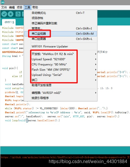
 准备好Arduino,打开串口监视器,选择正确的开发板,upload speed,端口号
 准备Esp8266模块,连接usb,gpio0 接GND,没接或没接好可能会报错。error: espcomm_open failed
 验证,上传。大概一到两分钟。左下角会显示“上传成功”.串口监视器会打印出 IP Address : 192.168.x.x
OTA更新,在第一次upload 后,端口号会增加一个192.168.x.x端口号,选择这个端口号。就可以实现OTA无线更新,不需要连接电脑,esp模块只需要5V,或3.3V供电即可。
五、 使用
手机或电脑打开 IP地址,如图所示
每个按钮实现一个功能。参考 void m()部分:修改相应的端口,定制各种模式。其他的,单个控制,或多组控制。
