一款mipi转lvds的lcd调试(lt8912b)
客户调试一款mipi转lvds的屏,使用的转换芯片是lt8912b。现将调试过程做个记录。
这款芯片之前在别的客户项目上调试过,但是这个客户的板子上存在如下问题:配置好设备树和驱动后,i2c读取lt8912b的寄存器0x9c-9f一直是ffff。咨询龙讯的FAE,原因就是没有识别到正确的MIPI信号。
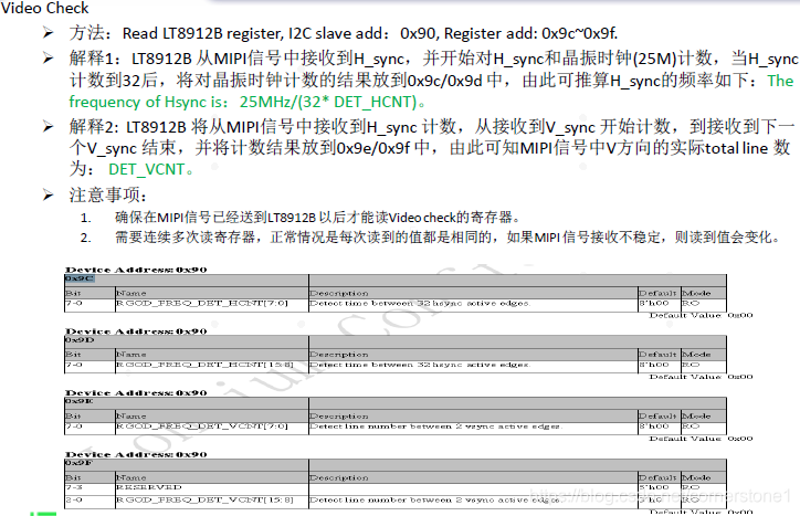
根据LT8912B的调试文档,如果HDMI 或者LVDS 没有图像输出,则首先应该check是否正确的接收到MIPI 信号,并稳定的恢复了时钟信号。
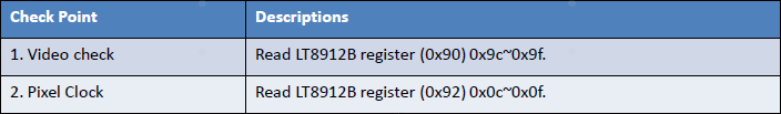
1.确认是否接收了正确的MIPI信号,通过读Video check 寄存器。
2.确认是否稳定的恢复了时钟信号,通过读Pixel Clock 寄存器。
分析过程:
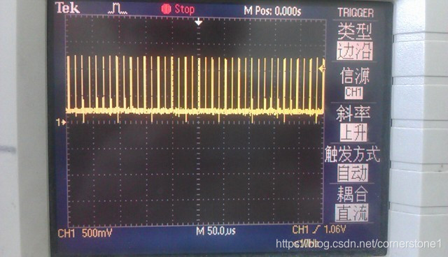
(1) 开始怀疑MIPI信号问题,测试MIPI clk是正常的:
下面是HS mode 和LP mode的时钟波形:
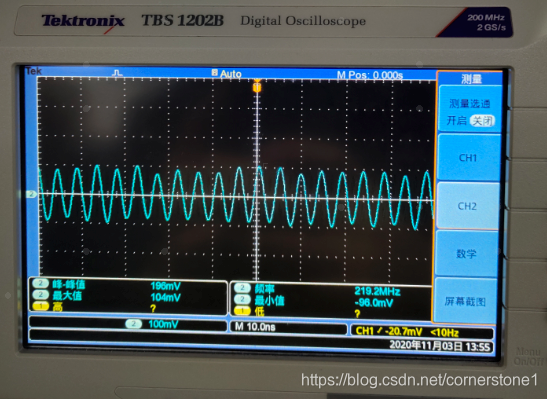
频率有219Mhz,这个和使用的屏的参数有关。
LT8912B 要求MIPI Clock Lane 是连续的,不要进入LP mode。
(2) 排除器件的影响,更换lt8912b后问题还是存在。
(3) 检查硬件,发现客户埋了个坑:把mipi的lane0正负接反了。
正常的寄存器数据如下:
[ 13.005051] <<-lt8912b->> [135]0x48 0xc1 = c1
[ 13.009326] <<-lt8912b->> [139]0x49 0xc1 = 0
[ 13.013383] <<-lt8912b->> [897]Enter read_para
[ 13.018072] <<-lt8912b->> [902][0x48] [09c] = 0x36
[ 13.031915] <<-lt8912b->> [902][0x48] [09d] = 0x63
[ 13.036251] <<-lt8912b->> [902][0x48] [09e] = 0xd
[ 13.040945] <<-lt8912b->> [902][0x48] [09f] = 0x2
[ 13.054823] <<-lt8912b->> [908][0x49] [0c] = 0xd3
[ 13.058967] <<-lt8912b->> [908][0x49] [0d] = 0x92
[ 13.080403] <<-lt8912b->> [908][0x49] [0e] = 0x29
[ 13.084488] <<-lt8912b->> [908][0x49] [0f] = 0x0
[ 13.091227] <<-lt8912b->> [912][0x49][0x13] mipi lane = 0x0
[ 13.110251] <<-lt8912b->> [914][0x49][0x15] lane swap = 0x20
识别到正确的mipi信号后,画面基本就出来了。剩下就是参数的优化了。如果lcd画面抖动的话,需要细调LCD参数。参考如下:
#ifdef MIPI_WXGA //1366x768
//H_act	 V_act	H_total	V_total	H_BP	H_sync	V_sync	V_BP
//{1366,768,	1500,	800,	64,	56,	3,	28};
// 1366x768 VESA Timing
static int mipi_dig_set_res(struct lt8912_data *data)
{
	int rc = 0;
	lt_debug("Enter mipi_dig_set_res MIPI_1366*768");
	data->lt8912_client->addr = 0x49;
	rc = lt8912_i2c_write_byte(data, 0x18, 0x38); // hsync width 56
	if (rc)
		return rc;
	rc = lt8912_i2c_write_byte(data, 0x19, 0x04); // vsync width 4
	if (rc)
		return rc;
	rc = lt8912_i2c_write_byte(data, 0x1c, 0x56); // Panel width LSB
	if (rc)
		return rc;
	rc = lt8912_i2c_write_byte(data, 0x1d, 0x05); // Panel width MSB-1366
	if (rc)
		return rc;
	rc = lt8912_i2c_write_byte(data, 0x2f, 0x0c); // FIFO Buff Length 12 --?
	if (rc)
		return rc;
	rc = lt8912_i2c_write_byte(data, 0x34, 0xDC); // H-TOTAL LSB
	if (rc)
		return rc;
	rc = lt8912_i2c_write_byte(data, 0x35, 0x05); // H-TOTAL MSB 1500
	if (rc)
		return rc;
	rc = lt8912_i2c_write_byte(data, 0x36, 0x20); // V-TOTAL LSB
	if (rc)
		return rc;
	rc = lt8912_i2c_write_byte(data, 0x37, 0x03); // V-TOTAL MSB 800
	if (rc)
		return rc;
	rc = lt8912_i2c_write_byte(data, 0x38, 0x1C); // VBP LSB 28
	if (rc)
		return rc;
	rc = lt8912_i2c_write_byte(data, 0x39, 0x00); // VBP MSB
	if (rc)
		return rc;
	rc = lt8912_i2c_write_byte(data, 0x3a, 0x00); // VFP LSB 0
	if (rc)
		return rc;
	rc = lt8912_i2c_write_byte(data, 0x3b, 0x00); // VFP MSB
	if (rc)
		return rc;
	rc = lt8912_i2c_write_byte(data, 0x3c, 0x40); // HBP LSB 64
	if (rc)
		return rc;
	rc = lt8912_i2c_write_byte(data, 0x3d, 0x00); // HBP MSB
	if (rc)
		return rc;
	rc = lt8912_i2c_write_byte(data, 0x3e, 0x0C); // HFP LSB 12
	if (rc)
		return rc;
	rc = lt8912_i2c_write_byte(data, 0x3f, 0x00); // HFP MSB
	if (rc)
		return rc;
	lt_debug("End   mipi_dig_set_res MIPI_1366*768");
	return 0;
}
#endif
可以使用i2c工具直接去修改寄存器来实时修改,观察参数的效果。