使用自制相机运行VINS-Mono
1 相机与IMU标定
VINSmono的安装这里就省略了,可以参考作者的github网页[2]
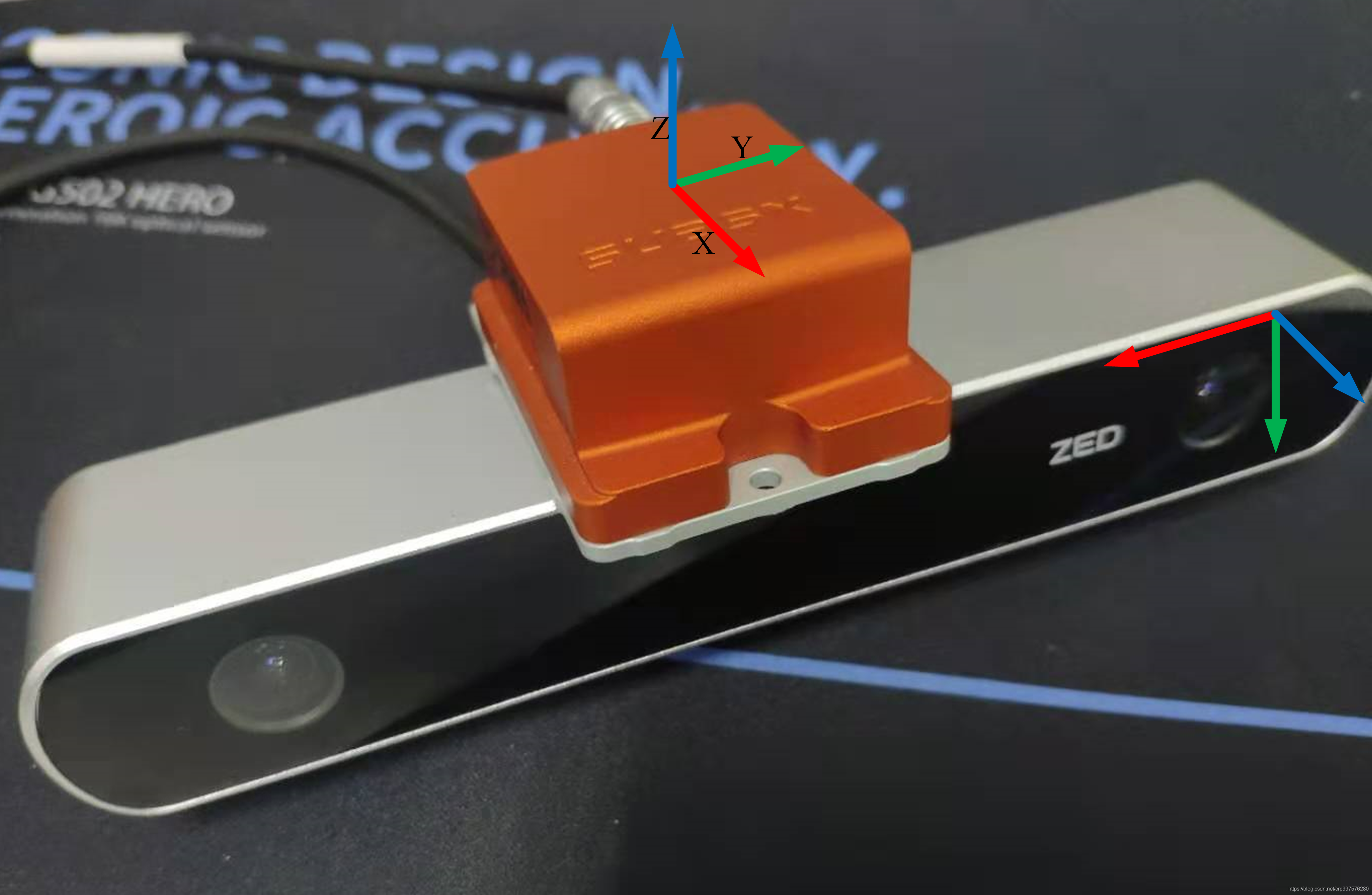
我所使用的是ZED相机和Xsens IMU, 相机和IMU的标定流程可以参考我之前的博客- 相机与IMU联合标定
2 自制相机测试
VINS-Mono的参数文件和msckf_vio的不同,msckf_vio可以直接使用kalibr校准输出的 T_cam_imu 矩阵,而VINS-mono则是使用的 T_imu_cam (Rotation from camera frame to imu frame) 需要对kalibr标定的结果求取逆矩阵。 这里我是直接复制到MATLAB中运算的。
在 cfg 文件夹下新建 zed_xsens_vins.yaml 文件,并写入以下内容:
%YAML:1.0
#common parameters
imu_topic: "/imu/data"
image_topic: "/camera/left/image_raw"
output_path: "/home/crp/catkin_vins"

#camera calibration
model_type: PINHOLE
camera_name: camera
image_width: 1280
image_height: 720
distortion_parameters:
   k1: -0.173485778
   k2: 0.0265451781212
   p1: 0.00042918874
   p2: -3.4873e-05
projection_parameters:
   fx: 693.131838769146
   fy: 692.5498277671763
   cx: 616.3486206381017
   cy: 379.6677572220899

# Extrinsic parameter between IMU and Camera.
estimate_extrinsic: 0   # 0  Have an accurate extrinsic parameters. We will trust the following imu^R_cam, imu^T_cam, don't change it.
                        # 1  Have an initial guess about extrinsic parameters. We will optimize around your initial guess.
                        # 2  Don't know anything about extrinsic parameters. You don't need to give R,T. We will try to calibrate it. Do some rotation movement at beginning.
#If you choose 0 or 1, you should write down the following matrix.
#Rotation from camera frame to imu frame, imu^R_cam
extrinsicRotation: !!opencv-matrix
   rows: 3
   cols: 3
   dt: d
   data: [-0.002694181974, -0.006483313053460837, 0.9999753537139497,
           -0.9999945422296715, 0.0019297348080352383, -0.0026817222894606196,
           -0.0019123008021141863, -0.999977121125988, -0.0064884767257617215]
#Translation from camera frame to imu frame, imu^T_cam
extrinsicTranslation: !!opencv-matrix
   rows: 3
   cols: 1
   dt: d
   data: [-0.006335432966116,0.067853027016898, -0.024648344205434]

#feature traker paprameters
max_cnt: 150            # max feature number in feature tracking
min_dist: 30            # min distance between two features
freq: 10                # frequence (Hz) of publish tracking result. At least 10Hz for good estimation. If set 0, the frequence will be same as raw image
F_threshold: 1.0        # ransac threshold (pixel)
show_track: 1           # publish tracking image as topic
equalize: 1             # if image is too dark or light, trun on equalize to find enough features
fisheye: 0              # if using fisheye, trun on it. A circle mask will be loaded to remove edge noisy points

#optimization parameters
max_solver_time: 0.04  # max solver itration time (ms), to guarantee real time
max_num_iterations: 8   # max solver itrations, to guarantee real time
keyframe_parallax: 10.0 # keyframe selection threshold (pixel)

#imu parameters       The more accurate parameters you provide, the better performance
acc_n: 0.08          # accelerometer measurement noise standard deviation. #0.2   0.04
gyr_n: 0.004         # gyroscope measurement noise standard deviation.     #0.05  0.004
acc_w: 0.00004         # accelerometer bias random work noise standard deviation.  #0.02
gyr_w: 2.0e-6       # gyroscope bias random work noise standard deviation.     #4.0e-5
g_norm: 9.81007     # gravity magnitude

#loop closure parameters
loop_closure: 1                    # start loop closure
load_previous_pose_graph: 0        # load and reuse previous pose graph; load from 'pose_graph_save_path'
fast_relocalization: 0             # useful in real-time and large project
pose_graph_save_path: "/home/crp/catkin_vins" # save and load path

#unsynchronization parameters
estimate_td: 0                      # online estimate time offset between camera and imu
td: 0.0                             # initial value of time offset. unit: s. readed image clock + td = real image clock (IMU clock)

#rolling shutter parameters
rolling_shutter: 0                  # 0: global shutter camera, 1: rolling shutter camera
rolling_shutter_tr: 0               # unit: s. rolling shutter read out time per frame (from data sheet).

#visualization parameters
save_image: 1                   # save image in pose graph for visualization prupose; you can close this function by setting 0
visualize_imu_forward: 0        # output imu forward propogation to achieve low latency and high frequence results
visualize_camera_size: 0.4      # size of camera marker in RVIZ
3 运行效果
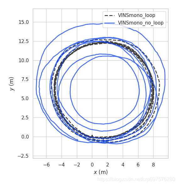
测试环境:我们使用白线在地面上画有一个半径为5M的圆,然后以手持相机的方式绕圆圈走,录制数据集。

然后利用 EVO 作图可以得到如下的轨迹
注意事项:
1)在使用VINSmono的时候要注意正确标定相机和IMU,平移参数可以通过目测的方式看看大概范围是否正确,旋转矩阵要注意看校准结果是否和真实传感器的坐标系是对应的。以此来判断校准参数是否正确。
2) kalibr校准输出的 T_cam_imu 矩阵,而VINS-mono则是使用的 T_imu_cam (Rotation from camera frame to imu frame) 需要对kalibr标定的结果求取逆矩阵
3) VINSmono对IMU比较敏感,如果IMU的质量不好的话也是可能导致系统无法运行
参考资料
[1] Qin T, Li P, Shen S. Vins-mono: A robust and versatile monocular visual-inertial state estimator[J]. IEEE Transactions on Robotics, 2018, 34(4): 1004-1020.
[2] https://github.com/HKUST-Aerial-Robotics/VINS-Mono
[3] (VINS-Mono运行与评测) https://blog.csdn.net/crp997576280/article/details/110485772
欢迎大家点赞在评论区交流讨论([email protected]) O(∩_∩)O
或者加群水一波(1149897304)