一、ADC,模拟数字转换器
1、定义
ADC(Analog to Digital Converter) :模数变换器;简称“模数转换器”,把模拟量转换为数字量的装置。
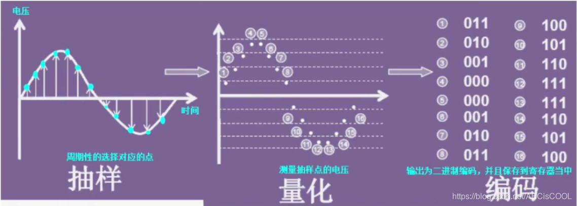
在计算机控制系统中,须经各种检测装置,以连续变化的电压或电流作为模拟量,随时提供被控制对象的有关参数(如速度、压力、温度等)而进行控制。计算机的输入必须是数字量,故需用模数转换器达到控制目的,过程有抽样、量化、编码(PCM编码,脉冲编码调制)。
其次简单介绍一下PCM编码:
(1)抽样:就是对模拟信号进行周期性扫描,把时间上连续的信号变成时间上离散的信号。该模拟信号经过抽样后述应当包含原信号中所有信息,也就是说能无失真的恢复原模拟信号。
(2)量化:就是把经过抽样得到的瞬时值将其幅度离散,即用一组规定的电平,把瞬时抽样值用最接近的电平值来表示,通常是用二进制表示。
(3)编码:就是用一组二进制码组来表示每一个有固定电平的量化值。然而,实际上量化是在编码过程中同时完成的,故编码过程也称为模/数变换,可记作A/D。
2、模拟信号
模拟信号是指用连续变化的物理量表示的信息,其信号的幅度,或频率,或相位随时间作连续变化,如目前广播的声音信号,或图像信号等。抓重点,连续的,如正弦波。
3、数字信号
数字信号指幅度的取值是离散的,幅值表示被限制在有限个数值之内。
二进制码就是一种数字信号。二进制码受噪声的影响小,易于有数字电路进行处理,所以得到了广泛的应用。抓重点,离散的,但在示波器中的方波一般指的是数字信号,把竖线去掉就是离散的了。
4、常用库函数
a.根据ADC_CommonInitTypeDef结构体,初始化ADC外设指定的参数(容易被忽略)
typedef struct
{


  uint32_t ADC_Mode;                      /*!< Configures the ADC to operate in
                                               independent or multi mode.
                                               This parameter can be a value of @ref ADC_Common_mode */
  uint32_t ADC_Prescaler;                 /*!< Select the frequency of the clock
                                               to the ADC. The clock is common for all the ADCs.
                                               This parameter can be a value of @ref ADC_Prescaler */
  uint32_t ADC_DMAAccessMode;             /*!< Configures the Direct memory access
                                              mode for multi ADC mode.
                                               This parameter can be a value of
                                               @ref ADC_Direct_memory_access_mode_for_multi_mode */
  uint32_t ADC_TwoSamplingDelay;          /*!< Configures the Delay between 2 sampling phases.
                                               This parameter can be a value of
                                               @ref ADC_delay_between_2_sampling_phases */

}ADC_CommonInitTypeDef;
- @param ADC_CommonInitStruct: pointer to an ADC_CommonInitTypeDef structure that contains the configuration information for All ADCs peripherals.
void ADC_CommonInit(ADC_CommonInitTypeDef* ADC_CommonInitStruct)
b.根据ADC_InitTypeDef结构体,初始化ADC外设指定的参数
typedef struct
{


  uint32_t ADC_Resolution;                /*!< Configures the ADC resolution dual mode.
                                               This parameter can be a value of @ref ADC_resolution */
  FunctionalState ADC_ScanConvMode;       /*!< Specifies whether the conversion
                                               is performed in Scan (multichannels)
                                               or Single (one channel) mode.
                                               This parameter can be set to ENABLE or DISABLE */
  FunctionalState ADC_ContinuousConvMode; /*!< Specifies whether the conversion
                                               is performed in Continuous or Single mode.
                                               This parameter can be set to ENABLE or DISABLE. */
  uint32_t ADC_ExternalTrigConvEdge;      /*!< Select the external trigger edge and
                                               enable the trigger of a regular group.
                                               This parameter can be a value of
                                               @ref ADC_external_trigger_edge_for_regular_channels_conversion */
  uint32_t ADC_ExternalTrigConv;          /*!< Select the external event used to trigger
                                               the start of conversion of a regular group.
                                               This parameter can be a value of
                                               @ref ADC_extrenal_trigger_sources_for_regular_channels_conversion */
  uint32_t ADC_DataAlign;                 /*!< Specifies whether the ADC data  alignment
                                               is left or right. This parameter can be
                                               a value of @ref ADC_data_align */
  uint8_t  ADC_NbrOfConversion;           /*!< Specifies the number of ADC conversions
                                               that will be done using the sequencer for
                                               regular channel group.
                                               This parameter must range from 1 to 16. */
}ADC_InitTypeDef;
- @brief Initializes the ADCx peripheral according to the specified parameters in the ADC_InitStruct.
- @note This function is used to configure the global features of the ADC ( Resolution and Data Alignment), however, the rest of the configuration
- parameters are specific to the regular channels group (scan mode activation, continuous mode activation, External trigger source and edge, number of conversion in the regular channels group sequencer).
-
@param ADCx: where x can be 1, 2 or 3 to select the ADC peripheral. - @param ADC_InitStruct: pointer to an ADC_InitTypeDef structure that contains the configuration information for the specified ADC peripheral.
void ADC_Init(ADC_TypeDef* ADCx, ADC_InitTypeDef* ADC_InitStruct)
c.为选定的ADC常规通道进行配置
-
@brief Configures for the selected ADC regular channel its corresponding rank in the sequencer and its sample time.
-
@param ADCx: where x can be 1, 2 or 3 to select the ADC peripheral.
-
@param ADC_Channel: the ADC channel to configure.
-
This parameter can be one of the following values:
-
@arg ADC_Channel_0~~~~~~arg ADC_Channel_18 -
@param Rank: The rank in the regular group sequencer.
-
This parameter must be between 1 to 16. -
@param ADC_SampleTime: The sample time value to be set for the selected channel.
-
This parameter can be one of the following values:
-
@arg ADC_SampleTime_3Cycles: Sample time equal to 3 cycles -
@arg ADC_SampleTime_15Cycles: Sample time equal to 15 cycles -
@arg ADC_SampleTime_28Cycles: Sample time equal to 28 cycles -
@arg ADC_SampleTime_56Cycles: Sample time equal to 56 cycles -
@arg ADC_SampleTime_84Cycles: Sample time equal to 84 cycles -
@arg ADC_SampleTime_112Cycles: Sample time equal to 112 cycles -
@arg ADC_SampleTime_144Cycles: Sample time equal to 144 cycles -
@arg ADC_SampleTime_480Cycles: Sample time equal to 480 cycles
void ADC_RegularChannelConfig(ADC_TypeDef* ADCx, uint8_t ADC_Channel, uint8_t Rank, uint8_t ADC_SampleTime)
例如是42MHZ,3cycle采集一次,那么时间就是3*1/42Mhz=0.07us,即三个ADC时钟的时间
d.使能指定的ADC的软件转换启动功能
- @param ADCx: where x can be 1, 2 or 3 to select the ADC peripheral.
void ADC_SoftwareStartConv(ADC_TypeDef* ADCx)
e.检查指定的ADC标志是否已设置
- @param ADCx: where x can be 1, 2 or 3 to select the ADC peripheral.
- @param ADC_FLAG: specifies the flag to check.
- This parameter can be one of the following values:
-
@arg ADC_FLAG_AWD: Analog watchdog flag -
@arg ADC_FLAG_EOC: End of conversion flag(结束标志位) -
@arg ADC_FLAG_JEOC: End of injected group conversion flag -
@arg ADC_FLAG_JSTRT: Start of injected group conversion flag -
@arg ADC_FLAG_STRT: Start of regular group conversion flag -
@arg ADC_FLAG_OVR: Overrun flag - @retval The new state of ADC_FLAG (SET or RESET).
FlagStatus ADC_GetFlagStatus(ADC_TypeDef* ADCx, uint8_t ADC_FLAG)
具体的函数在固件库手册找不到的时候,可以在对应的stm32f4xx_adc.c中查找,function列表的函数
f.返回ADC对应通道的测量数据
- @param ADCx: where x can be 1, 2 or 3 to select the ADC peripheral.
- @retval The Data conversion value.
uint16_t ADC_GetConversionValue(ADC_TypeDef* ADCx)
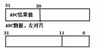
g.左对齐和右对齐
4、STM32F4的ADC最高分辨率是12位,即最大数值达到4095,
12位分辨率最低可以测量:3300mV/4095=0.8mV
10位分辨率最低可以测量:3300mV/1024=3.22mV
所以分辨率越高,精度越高。
5、测量结果转换为电压值
被测量电压 = ADC对应通道的测量数据 * 参考电压 /4095.
一般参考电压为3.3V,用3300mV来计算,主要由自己决定。
正常输出电压的例子:
ADC硬件的时钟记得开启(易漏点)
#include "stm32f4xx.h"
#include "stm32f4xx_gpio.h"
#include "stm32f4xx_rcc.h"
#include "stm32f4xx_usart.h"
#include "stdio.h"
#include "sys.h"

static GPIO_InitTypeDef  	GPIO_InitStructure;
static USART_InitTypeDef 	USART_InitStructure;
static NVIC_InitTypeDef 	NVIC_InitStructure;

static ADC_InitTypeDef       ADC_InitStructure;
static ADC_CommonInitTypeDef ADC_CommonInitStructure;


//重定义fputc函数
int fputc(int ch, FILE *f)
{


	USART_SendData(USART1,ch);
	while(USART_GetFlagStatus(USART1,USART_FLAG_TXE)==RESET);

	return ch;
}

void delay_us(uint32_t nus)
{


	uint32_t temp;
	SysTick->LOAD =SystemCoreClock/8/1000000*nus; 	//时间加载
	SysTick->VAL  =0x00;        					//清空计数器
	SysTick->CTRL|=SysTick_CTRL_ENABLE_Msk ; 		//使能滴答定时器开始倒数
	do
	{


		temp=SysTick->CTRL;
	}while((temp&0x01)&&!(temp&(1<<16)));			//等待时间到达
	SysTick->CTRL&=~SysTick_CTRL_ENABLE_Msk; 		//关闭计数器
	SysTick->VAL =0X00;       						//清空计数器
}

void delay_ms(uint16_t nms)
{


	uint32_t temp;
	SysTick->LOAD=SystemCoreClock/8/1000*nms;		//时间加载(SysTick->LOAD为24bit)
	SysTick->VAL =0x00;           					//清空计数器
	SysTick->CTRL|=SysTick_CTRL_ENABLE_Msk ;    	//能滴答定时器开始倒数
	do
	{


		temp=SysTick->CTRL;
	}while((temp&0x01)&&!(temp&(1<<16)));			//等待时间到达
	SysTick->CTRL&=~SysTick_CTRL_ENABLE_Msk;    	//关闭计数器
	SysTick->VAL =0X00;     		  				//清空计数器
}


void USART1_Init(uint32_t baud)
{


	RCC_AHB1PeriphClockCmd(RCC_AHB1Periph_GPIOA,ENABLE); 							//使能GPIOA时钟
	RCC_APB2PeriphClockCmd(RCC_APB2Periph_USART1,ENABLE);							//使能USART1时钟

	//串口1对应引脚复用映射
	GPIO_PinAFConfig(GPIOA,GPIO_PinSource9,GPIO_AF_USART1); 						//GPIOA9复用为USART1
	GPIO_PinAFConfig(GPIOA,GPIO_PinSource10,GPIO_AF_USART1); 						//GPIOA10复用为USART1

	//USART1端口配置
	GPIO_InitStructure.GPIO_Pin = GPIO_Pin_9 | GPIO_Pin_10; 						//GPIOA9与GPIOA10
	GPIO_InitStructure.GPIO_Mode = GPIO_Mode_AF;									//复用功能
	GPIO_InitStructure.GPIO_Speed = GPIO_Speed_50MHz;								//速度50MHz
	GPIO_InitStructure.GPIO_OType = GPIO_OType_PP; 									//推挽复用输出
	GPIO_InitStructure.GPIO_PuPd = GPIO_PuPd_UP; 									//上拉
	GPIO_Init(GPIOA,&GPIO_InitStructure); 											//初始化PA9,PA10

	//USART1 初始化设置
	USART_InitStructure.USART_BaudRate = baud;										//波特率设置
	USART_InitStructure.USART_WordLength = USART_WordLength_8b;						//字长为8位数据格式
	USART_InitStructure.USART_StopBits = USART_StopBits_1;							//一个停止位
	USART_InitStructure.USART_Parity = USART_Parity_No;								//无奇偶校验位
	USART_InitStructure.USART_HardwareFlowControl = USART_HardwareFlowControl_None;	//无硬件数据流控制
	USART_InitStructure.USART_Mode = USART_Mode_Rx | USART_Mode_Tx;					//收发模式
	USART_Init(USART1, &USART_InitStructure); 										//初始化串口1

	USART_Cmd(USART1, ENABLE);  													//使能串口1

	USART_ITConfig(USART1, USART_IT_RXNE, ENABLE);									//开启相关中断

	//Usart1 NVIC 配置
	NVIC_InitStructure.NVIC_IRQChannel = USART1_IRQn;								//串口1中断通道
	NVIC_InitStructure.NVIC_IRQChannelPreemptionPriority=3;							//抢占优先级3
	NVIC_InitStructure.NVIC_IRQChannelSubPriority =3;								//子优先级3
	NVIC_InitStructure.NVIC_IRQChannelCmd = ENABLE;									//IRQ通道使能
	NVIC_Init(&NVIC_InitStructure);													//根据指定的参数初始化VIC寄存器
}

void adc_init(void)
{


	//使能GPIOA的硬件时钟
	RCC_AHB1PeriphClockCmd(RCC_AHB1Periph_GPIOA, ENABLE);

	//使能ADC1硬件时钟
	RCC_APB2PeriphClockCmd(RCC_APB2Periph_ADC1, ENABLE);

	/* 配置ADC1通道5为模拟输入引脚 */
	GPIO_InitStructure.GPIO_Pin = GPIO_Pin_5;
	//引脚设置为模拟输入,能够识别更加广范围的电平(0V~3.3V任何电压)
	GPIO_InitStructure.GPIO_Mode = GPIO_Mode_AN;
	GPIO_InitStructure.GPIO_PuPd = GPIO_PuPd_NOPULL ;
	GPIO_Init(GPIOA, &GPIO_InitStructure);

	 ADC常规的初始化

	/*独立模式,在当前的通道5只采用1个ADC硬件进行工作*/
	ADC_CommonInitStructure.ADC_Mode = ADC_Mode_Independent;
	ADC_CommonInitStructure.ADC_Prescaler = ADC_Prescaler_Div2;						//ADC硬件的工作时钟= APB2(84MHz)/2=42MHz
	ADC_CommonInitStructure.ADC_DMAAccessMode = ADC_DMAAccessMode_Disabled;			//禁止DMA
	//ADC_CommonInitStructure.ADC_TwoSamplingDelay = ADC_TwoSamplingDelay_5Cycles;	//如果采用多个ADC对某一个通道进行采样的时候,才需要设置
	ADC_CommonInit(&ADC_CommonInitStructure);


	 ADC1初始化
	 /*12位分辨率*/
	ADC_InitStructure.ADC_Resolution = ADC_Resolution_12b;
	//因没有使用DMA,则不需要使用自动扫描模式。当前使用软件触发一次,则扫描一次
	ADC_InitStructure.ADC_ScanConvMode = DISABLE;
	//模拟数字转换器一直工作
	ADC_InitStructure.ADC_ContinuousConvMode = ENABLE;
	//禁止触发检测,不需要外部引脚电平识别来让ADC硬件工作
	ADC_InitStructure.ADC_ExternalTrigConvEdge = ADC_ExternalTrigConvEdge_None;
	//右对齐
	ADC_InitStructure.ADC_DataAlign = ADC_DataAlign_Right;
	//执行一次转换结果
	ADC_InitStructure.ADC_NbrOfConversion = 1;
	ADC_Init(ADC1, &ADC_InitStructure);

	/* 指定ADC1常规通道5的采样时间,采样时间=3个ADC时钟时间,这是最短的时间*/
	ADC_RegularChannelConfig(ADC1, ADC_Channel_5, 1, ADC_SampleTime_3Cycles);

	/* Enable ADC1 */
	ADC_Cmd(ADC1, ENABLE);


}


int main(void)
{


	uint32_t adc_val,adc_vol;
	//系统定时器初始化,时钟源来自HCLK,且进行8分频,
	//系统定时器时钟频率=168MHz/8=21MHz
	SysTick_CLKSourceConfig(SysTick_CLKSource_HCLK_Div8);

	//设置中断优先级分组2
	NVIC_PriorityGroupConfig(NVIC_PriorityGroup_2);

	//串口1,波特率115200bps,开启接收中断
	USART1_Init(115200);


	//ADC初始化
	adc_init();

	while(1)
	{


		/* 1---启动ADC1进行转换*/
		ADC_SoftwareStartConv(ADC1);

		/*2---等待转换结束,结束时标志位置1,1!=0,跳出循环*/
		while(ADC_GetFlagStatus(ADC1,ADC_FLAG_EOC)==RESET);

		/*3---获取ADC转换后的数值*/
		adc_val=ADC_GetConversionValue(ADC1);

		//将ADC输出的结果值转换位电压值,打印
		adc_vol = adc_val*3300/4095;
		printf("vol = %dmv\r\n",adc_vol);
		delay_ms(500);

	}
}
//串口1中断服务程序
void USART1_IRQHandler(void)
{


	uint8_t d;

	if(USART_GetITStatus(USART1, USART_IT_RXNE) != RESET)  //接收中断
	{


		d = USART_ReceiveData(USART1);
	}
}
#后续练习
调整可调电阻以控制LED灯的亮度,ADC获取电压值,根据电压值实现PWM占空比。
部分代码:
void tim14_init(void)
{


	TIM_TimeBaseInitTypeDef  		TIM_TimeBaseStructure;
	TIM_OCInitTypeDef  				  TIM_OCInitStructure;
	/* GPIOF clock enable */
	RCC_AHB1PeriphClockCmd(RCC_AHB1Periph_GPIOF, ENABLE);

	/* GPIOF Configuration: TIM14 CH1 (PF9) */
	GPIO_InitStructure.GPIO_Pin = GPIO_Pin_9 ;
	GPIO_InitStructure.GPIO_Mode = GPIO_Mode_AF;			//复用功能,使用引脚的第二功能
	GPIO_InitStructure.GPIO_Speed = GPIO_Speed_100MHz;
	GPIO_InitStructure.GPIO_OType = GPIO_OType_PP;
	GPIO_InitStructure.GPIO_PuPd = GPIO_PuPd_UP ;
	GPIO_Init(GPIOF, &GPIO_InitStructure);

	/* Connect TIM pins to AF9 */
	GPIO_PinAFConfig(GPIOF, GPIO_PinSource9, GPIO_AF_TIM14);

	/* TIM14 clock enable */
	RCC_APB1PeriphClockCmd(RCC_APB1Periph_TIM14, ENABLE);


	/* Time base configuration,100Hz*/
	TIM_TimeBaseStructure.TIM_Period = (10000/100)-1;					//定时计数值,100Hz
	TIM_TimeBaseStructure.TIM_Prescaler = 8400;							//预分频值
	TIM_TimeBaseStructure.TIM_ClockDivision = TIM_CKD_DIV1;				//再次进行1分频
	TIM_TimeBaseStructure.TIM_CounterMode = TIM_CounterMode_Up;			//向上计数
	TIM_TimeBaseInit(TIM14, &TIM_TimeBaseStructure);


	/* PWM1 Mode configuration: Channel1 */
	TIM_OCInitStructure.TIM_OCMode = TIM_OCMode_PWM1;
	TIM_OCInitStructure.TIM_OutputState = TIM_OutputState_Enable;
	TIM_OCInitStructure.TIM_OCPolarity = TIM_OCPolarity_High;
	TIM_OC1Init(TIM14, &TIM_OCInitStructure);


	TIM_OC1PreloadConfig(TIM14, TIM_OCPreload_Enable);					//自动重载初值,不断输出PWM脉冲
	TIM_ARRPreloadConfig(TIM14, ENABLE);								//自动重载使能

	/* TIM14 enable counter */
	TIM_Cmd(TIM14, ENABLE);

}

int main(void)
{


	uint32_t adc_val,adc_vol,pwm_cmp=0;;

	//系统时钟的时钟源=168MHz/8=21MHz
	SysTick_CLKSourceConfig(SysTick_CLKSource_HCLK_Div8);

	//串口初始化,波特率为115200bps
	usart1_init(115200);

	//adc初始化,12位精度
	adc_init();

	//定时器14初始化为PWM,使用PWM通道1,当前频率为100Hz
	tim14_init();


	while(1)
	{


		/* Start ADC Software Conversion ,启动ADC*/
		ADC_SoftwareStartConv(ADC1);

		//等待转换结束
		while(ADC_GetFlagStatus(ADC1,ADC_FLAG_EOC)==RESET);

		//获取ADC转换后的数值
		adc_val=ADC_GetConversionValue(ADC1);

		//将ADC的数值转换为电压值
		adc_vol = adc_val *3300/4095;

		printf("vol=%dmv\r\n",adc_vol);

		//设置比较值
		pwm_cmp = (adc_vol/3300)*100 ;//占用当前比例是多少,所以要乘100

		TIM_SetCompare1(TIM14,pwm_cmp);

		printf("pwm compare=%d\r\n",pwm_cmp);


		delay_ms(500);

	}
}


void USART1_IRQHandler(void)
{


	uint8_t d;

	/* USART in Receiver mode */
	if (USART_GetITStatus(USART1, USART_IT_RXNE) == SET)
	{


		d= USART_ReceiveData(USART1);

		USART_SendData(USART1, d);

		/* Loop until the end of transmission ,直到串口数据帧全部发送完毕*/
		while (USART_GetFlagStatus(USART1, USART_FLAG_TC) == RESET);

	}

}