1.软件版本
MATLAB2021a
2.本算法理论知识
[1]钱坤. 基于MSER和遗传优化SVM的交通标志识别的研究[D]. 大连理工大学.
[2]王斌, 常发亮, 刘春生. 基于MSER和SVM的快速交通标志检测[J]. 光电子.激光, 2016.
3.部分源码
%%%%%%%%%%%%%%%%%%%%%%%%%%%%%%%%%%%%%%%%%%%%%%%%%%%%%%%%%%%%%%%%%%%%%%%%%%%%%%%%
% %
% MSER algorithm - Linear Time MSER %
clc
clear
close all
tic
% Read input image
img = imread('img/smp_6.jpg');
height = size(img,1);
width = size(img,2);
total_pixels_img = width*height;
usage = 'segmented'; % select between segmented or gray scale
% image as input: 'segmented' / 'gray'
% Parameters to set
min_area_mser = 1000;
max_area_mser = 1000000;
mser_p.delta = 2;
mser_p.min_area = 0.00001*width*height;
mser_p.max_area = 0.25*width*height;
mser_p.max_variation = 0.5;
mser_p.min_diversity = 0.33;
color_of_interest = 'blue'; % Options are: red, green, blue
color_threshold = 100; % range from 0-255
ratio = 1.2; % ration between color interest and
% others: 20%
%%%%%%%%%%%%%%%%%%%%%%%%%%%%%%%%%%%%%%%%%%%%%%%%%%%%%%%%%%%%%%%%%%%%%%%%%%%%%%%%
% INIT ALGORITHM
% 1) Select input image to process if it's gray or segmented and create a single
% row vector with the image
switch usage
case 'segmented'
% Simple segmentation by color threshold
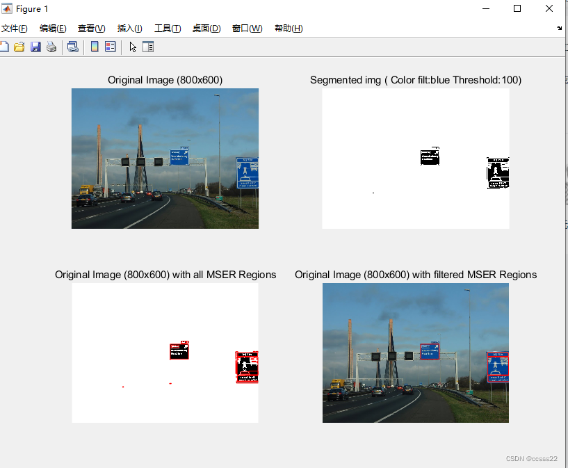
img_seg = f_seg(img, color_threshold, color_of_interest, ratio);
subplot(2,2,1);
imshow(img);
title(['Original Image (' num2str(width) 'x' num2str(height) ')']);
subplot(2,2,2);
imshow(img_seg);
title(['Segmented img ( Color filt:' color_of_interest ' Threshold:' ...
num2str(color_threshold) ')']);
i = 1;
for y=1:height
for x=1:width
if img_seg(y,x) == 0
img_scan(i,1) = 1;
else
img_scan(i,1) = img_seg(y,x);
end
i=i+1;
end
end
img_selected = img_seg;
case 'gray'
% Image converted in gray scale
img_grey = rgb2gray(img);
subplot(2,2,1);
imshow(img);
title(['Original Image (' num2str(width) 'x' num2str(height) ')']);
subplot(2,2,2);
imshow(img_grey);
title(['Gray Image (' num2str(size(img_grey,2)) 'x' ...
num2str(size(img_grey,1)) ')']);
i = 1;
for y=1:height
for x=1:width
if img_grey(y,x) == 0
img_scan(i,1) = 1;
else
img_scan(i,1) = img_grey(y,x);
end
i=i+1;
end
end
img_selected = img_grey;
end
% 2) Create the bin mask with accessed pixels
bin_mask_access = zeros(total_pixels_img,1);
% 3) Initialize control variables
priority = 256; % Variable that defines the smallest
% 'dark' pixel
current_pixel = 1;
current_edge = 0;
current_level = img_scan(current_pixel);
bin_mask_access(current_pixel) = 1;
index_regions = 0;
g_index_stack = 0;
% Create the LIFO for the 256 gray leves
for i=1:256
boundary_pixels(i) = CStack();
end
% Insert into the tree the most 'bright' pixel that equivalent to 256
g_index_stack = g_index_stack + 1;
index_regions = index_regions + 1;
region_stack(index_regions).level = 256;
region_stack(index_regions).area = 0;
region_stack(index_regions).mom(1) = 0;
region_stack(index_regions).mom(2) = 0;
region_stack(index_regions).mom(3) = 0;
region_stack(index_regions).mom(4) = 0;
region_stack(index_regions).mom(5) = 0;
region_stack(index_regions).variation_mser = 999999;
region_stack(index_regions).stable = 0;
region_stack(index_regions).parent = 0;
region_stack(index_regions).child = 0;
region_stack(index_regions).next = 0;
% This is an auxiliary vector (LIFO) to store the regions pushed and not process
% ed by the function 'process_stack' yet, which defines the parent and child nod
% es. In normal behavior this must inflate and deinflate during the image proces
% sing
stack(g_index_stack).node = index_regions;
% Each region_stack has a correspondent rect that represents the rectangle assoc
% iated with that region, it facilitates in the later step
rect(index_regions).top = Inf;
rect(index_regions).bottom = 0;
rect(index_regions).left = Inf;
rect(index_regions).right = 0;
rect(index_regions).draw = 1;
% Insert into the tree the first region for the first pixel level in the image
g_index_stack = g_index_stack + 1;
index_regions = index_regions + 1;
region_stack(index_regions).level = current_level;
region_stack(index_regions).area = 0;
region_stack(index_regions).mom(1) = 0;
region_stack(index_regions).mom(2) = 0;
region_stack(index_regions).mom(3) = 0;
region_stack(index_regions).mom(4) = 0;
region_stack(index_regions).mom(5) = 0;
region_stack(index_regions).variation_mser = 999999;
region_stack(index_regions).stable = 0;
region_stack(index_regions).parent = 0;
region_stack(index_regions).child = 0;
region_stack(index_regions).next = 0;
stack(g_index_stack).node = index_regions;
rect(index_regions).top = Inf;
rect(index_regions).bottom = 0;
rect(index_regions).left = Inf;
rect(index_regions).right = 0;
rect(index_regions).draw = 1;
% 4) Run the main algorithm that will scan all pixels inside the image
gCounter = 0;
done = 0;
while (done == 0)
gCounter = gCounter+1; % ...it'll always be the total_pixels_img
% While loop to scan all edges of the pixel in analisys
while current_edge < 4
% ...get the neighbor pixel according to correspondent edge in the BIG row v
% ector that contains all pixels
neighbor_pixel = f_neighbor_pixel(current_pixel,current_edge,width,height);
if (bin_mask_access(neighbor_pixel) == 0)
neighbor_level = img_scan(neighbor_pixel,1);
bin_mask_access(neighbor_pixel) = 1;
% If the neighbor pixel has a 'lowest (black)' level than the current one,
% let push a new region and define as our new current pixel
if (neighbor_level < current_level)
% In this step we need to store the old current pixel and its current ed
% ge and to execute this, we are joining with OR - logical operation the
% two informations with this approach:
%
% 8 bits 4 bits
% Pixel to map after -> current pixel position current edge
% (remember that now, this is) (we add +1)
% (just a number in a row) (because we want)
% (the next edge)
%
% Example:
% CUR_PIXEL (8) 1010 1010 << 4
% EDGE (4) + 1111
% Later processing (12) 1010 1010 1111
boundary_pixels(current_level).push(bitor(bitshift(current_pixel,4), ...
(current_edge+1)));
% ..always define priority as the 'darkest' pixel founded, because we'll
% search for that pixel in the boundary stack after if we do not find an
% y pixel lowest (black) in the edges
if (current_level < priority)
priority = current_level;
end
current_pixel = neighbor_pixel;
current_edge = 0;
current_level = neighbor_level;
% Push a new region with the new 'darkest' pixel founded
index_regions = index_regions + 1;
region_stack(index_regions).level = current_level;
region_stack(index_regions).area = 0;
region_stack(index_regions).mom(1) = 0;
region_stack(index_regions).mom(2) = 0;
region_stack(index_regions).mom(3) = 0;
region_stack(index_regions).mom(4) = 0;
region_stack(index_regions).mom(5) = 0;
region_stack(index_regions).variation_mser = 999999;
region_stack(index_regions).stable = 0;
region_stack(index_regions).parent = 0;
region_stack(index_regions).child = 0;
region_stack(index_regions).next = 0;
g_index_stack = g_index_stack + 1;
stack(g_index_stack).node = index_regions;
% ..and its rectangle combined
rect(index_regions).top = Inf;
rect(index_regions).bottom = 0;
rect(index_regions).left = Inf;
rect(index_regions).right = 0;
rect(index_regions).draw = 1;
continue;
end
% If the current pixel is the 'lowest (black)', store the neighboor for la
% ter search iteration
boundary_pixels(neighbor_level).push(bitor(bitshift(neighbor_pixel,4),0));
if (neighbor_level < priority)
priority = neighbor_level;
end
end
current_edge = current_edge + 1;
end
% We need to discover in the MxN representation, the value of the pixel for im
% age math processing, for later computing
x = mod(current_pixel, width); % Give us the offset in the line of the image
if x == 0
x = width;
end
y = floor(current_pixel/width);
% As the MSER alg. we need to accumulate the latest pixel in the latest region
[region_stack rect] = f_accumulate(region_stack, rect, stack, ...
g_index_stack, x, y);
% If our priority is 256 we don't have a lowest pixel anymore, then we finish!
% ..and we need to process all stack creating the tree with the regions to be
% this way:
% Example:
% ________________256_______________
% | | | |
% _243_ _ 251_ _202_ _215_
% | | | | | | | |
% 145 20 200 10 198 52 20 112
% ...................................................
%
% PARENT
% |
% NODE
% / \
% NEXT CHILD
%
if (priority == 256)
% PROCESS STACK
new_pixel_grey_level = 256; % Passing 256 as the new pixel grey level matche
% s to create the root tree node
[region_stack ...
rect ...
index_regions ...
g_index_stack ...
stack] = f_process_stack(new_pixel_grey_level, ...
region_stack, ...
stack, ...
g_index_stack, ...
index_regions, ...
rect);
done = 1;
break;
end
% Remove the pixel with lowest (black) value stored in the stack to process...
% we remove top because it's a LIFO
pixel_component = boundary_pixels(priority).top();
% Undo the concatenation made previous before
current_pixel = bitshift(pixel_component,-4);
current_edge = bitand(pixel_component,15);
boundary_pixels(priority).pop();
% If we empty the stack in that black level, we need to increase the priority
while (boundary_pixels(priority).isempty() && (priority < 256))
priority = double(priority + 1);
end
% Get the black level for our new current pixel
new_pixel_grey_level = img_scan(current_pixel);
if (new_pixel_grey_level ~= current_level)
% PROCESS STACK
[region_stack ...
rect ...
index_regions ...
g_index_stack ...
stack] = f_process_stack(new_pixel_grey_level, ...
region_stack, ...
stack, ...
g_index_stack, ...
index_regions, ...
rect);
current_level = new_pixel_grey_level;
end
end
% END OF MAIN ALGORITHM
%%%%%%%%%%%%%%%%%%%%%%%%%%%%%%%%%%%%%%%%%%%%%%%%%%%%%%%%%%%%%%%%%%%%%%%%%%%%%%%%
% Post-processing step
% 5) Stable analisys of each region to determine the MSER regions
stable_counter = 0;
for i=1:size(region_stack,2)
reg = region_stack(i);
parent = region_stack(i);
while (parent.parent && region_stack(parent.parent).level <= reg.level + ...
mser_p.delta)
parent = region_stack(parent.parent);
end
reg.variation_mser = (parent.area - reg.area)/reg.area;
reg.stable = (reg.area >= mser_p.min_area) && ...
(reg.area <= mser_p.max_area) && (reg.variation_mser <= ...
mser_p.max_variation);
id = reg.parent;
if id ~= 0
parent = region_stack(id);
while (parent.parent && reg.area > mser_p.min_diversity*parent.area)
if(parent.variation_mser <= reg.variation_mser)
reg.stable = false;
end
if(reg.variation_mser < parent.variation_mser)
parent.stable = false;
end
rect(id).stable = parent.stable;
region_stack(id) = parent;
id = parent.parent;
parent = region_stack(id);
end
end
if (reg.stable == 1)
stable_counter = stable_counter + 1;
end
rect(i).stable = reg.stable;
region_stack(i) = reg;
end
% Saving just the stable regions
t = 0;
for p=1:size(rect,2)
if(rect(p).stable == 1)
t = t+1;
tmp(t) = rect(p);
end
end
rect = tmp;
subplot(2,2,3);
imshow(img_selected);
title(['Original Image (' num2str(width) 'x' num2str(height) ...
') with all MSER Regions']);
k=0;
for i=1:size(rect,2)
if (rect(i).draw == 1)
k=k+1;
width_n = rect(i).right-rect(i).left;
height_n = rect(i).bottom-rect(i).top;
rectangle('Position',[rect(i).left rect(i).top width_n height_n], ...
'EdgeColor','r');
end
end
% 6) Filtering just the rectangles with some specific area range
for i=1:size(rect,2)
rect(i).height = rect(i).bottom - rect(i).top;
rect(i).width = rect(i).right - rect(i).left;
rect(i).size = rect(i).height*rect(i).width;
if (rect(i).size > min_area_mser && rect(i).size < max_area_mser)
rect(i).draw = 1;
else
rect(i).draw = 0;
end
end
subplot(2,2,4);
imshow(img);
title(['Original Image (' num2str(width) 'x' num2str(height) ...
') with filtered MSER Regions']);
% 7) Draw the rectangles in the original image
k=0;
for i=1:size(rect,2)
if (rect(i).draw == 1)
k=k+1;
width_n = rect(i).right-rect(i).left;
height_n = rect(i).bottom-rect(i).top;
rectangle('Position',[rect(i).left rect(i).top width_n height_n], ...
'EdgeColor','r');
end
end
time_p = toc;
% 8) Reports
fprintf('\tConclusion Reports');
fprintf('\nImage size: Width=%d x Height=%d',width,height);
fprintf('\nTotal number of pixels: %d',total_pixels_img);
fprintf('\nFounded regions: %d',index_regions);
fprintf('\nStable regions: %d',stable_counter);
fprintf('\nRectangles drawed: %d', k);
fprintf('\nTime to process the image: %d seconds', time_p);
fprintf('\nMSER Parameters: ');
mser_p
4.仿真
D238