作者:沉尸([email protected])
本章专门分析函数“control_loop_cb()”的执行
1)搞清楚在函数中做了哪些工作
2)这些工作中哪个环节等待了“TIM8的update事件”,这也是上一篇文章:
《ODrive0.5.5源码分析(2) 时钟和定时器》
中没有进行细化分析的内容。
这里先贴出源代码:
来自“MotorControl\main.cpp”
| 364 365 366 367 368 369 370 371 372 373 374 375 376 377 378 379 380 381 382 383 384 385 386 387 388 389 390 391 392 393 394 395 396 397 398 399 400 401 402 403 404 405 406 407 408 409 410 411 412 413 414 415 416 417 418 419 420 421 422 423 424 425 426 427 428 429 430 431 432 433 434 435 436 437 438 439 440 441 442 443 444 445 446 447 448 449 450 451 452 453 454 455 456 457 458 459 460 461 462 463 464 465 466 |
void ODrive::control_loop_cb(uint32_t timestamp) { last_update_timestamp_ = timestamp; n_evt_control_loop_++; // TODO: use a configurable component list for most of the following things MEASURE_TIME(task_times_.control_loop_misc) { // Reset all output ports so that we are certain about the freshness of // all values that we use. // If we forget to reset a value here the worst that can happen is that // this safety check doesn't work. // TODO: maybe we should add a check to output ports that prevents // double-setting the value. for (auto& axis: axes) { axis.acim_estimator_.slip_vel_.reset(); axis.acim_estimator_.stator_phase_vel_.reset(); axis.acim_estimator_.stator_phase_.reset(); axis.controller_.torque_output_.reset(); axis.encoder_.phase_.reset(); axis.encoder_.phase_vel_.reset(); axis.encoder_.pos_estimate_.reset(); axis.encoder_.vel_estimate_.reset(); axis.encoder_.pos_circular_.reset(); axis.motor_.Vdq_setpoint_.reset(); axis.motor_.Idq_setpoint_.reset(); axis.open_loop_controller_.Idq_setpoint_.reset(); axis.open_loop_controller_.Vdq_setpoint_.reset(); axis.open_loop_controller_.phase_.reset(); axis.open_loop_controller_.phase_vel_.reset(); axis.open_loop_controller_.total_distance_.reset(); axis.sensorless_estimator_.phase_.reset(); axis.sensorless_estimator_.phase_vel_.reset(); axis.sensorless_estimator_.vel_estimate_.reset(); } uart_poll(); odrv.oscilloscope_.update(); } for (auto& axis : axes) { MEASURE_TIME(axis.task_times_.endstop_update) { axis.min_endstop_.update(); axis.max_endstop_.update(); } } MEASURE_TIME(task_times_.control_loop_checks) { for (auto& axis: axes) { // look for errors at axis level and also all subcomponents bool checks_ok = axis.do_checks(timestamp); // make sure the watchdog is being fed. bool watchdog_ok = axis.watchdog_check(); if (!checks_ok || !watchdog_ok) { axis.motor_.disarm(); } } } for (auto& axis: axes) { // Sub-components should use set_error which will propegate to this error_ MEASURE_TIME(axis.task_times_.thermistor_update) { axis.motor_.fet_thermistor_.update(); axis.motor_.motor_thermistor_.update(); } MEASURE_TIME(axis.task_times_.encoder_update) axis.encoder_.update(); } // Controller of either axis might use the encoder estimate of the other // axis so we process both encoders before we continue. for (auto& axis: axes) { MEASURE_TIME(axis.task_times_.sensorless_estimator_update) axis.sensorless_estimator_.update(); MEASURE_TIME(axis.task_times_.controller_update) { if (!axis.controller_.update()) { // uses position and velocity from encoder axis.error_ |= Axis::ERROR_CONTROLLER_FAILED; } } MEASURE_TIME(axis.task_times_.open_loop_controller_update) axis.open_loop_controller_.update(timestamp); MEASURE_TIME(axis.task_times_.motor_update) axis.motor_.update(timestamp); // uses torque from controller and phase_vel from encoder MEASURE_TIME(axis.task_times_.current_controller_update) axis.motor_.current_control_.update(timestamp); // uses the output of controller_ or open_loop_contoller_ and encoder_ or sensorless_estimator_ or acim_estimator_ } // Tell the axis threads that the control loop has finished for (auto& axis: axes) { if (axis.thread_id_) { osSignalSet(axis.thread_id_, 0x0001); } } get_gpio(odrv.config_.error_gpio_pin).write(odrv.any_error()); } |
Ln377 ~ Ln397:
将一系列的变量“reset()”,这些变量有一个共同的特点,都是模板类对象:
OutputPort<T>
这里需要将模板“OutputPort”认真理解一下,c++基础有点弱的需要好好补习一下。
Ln399:
uart_poll();

调用“uart_poll()”,会发出消息,消息id = uart_event_queue,消息info = 1。
线程“uart_server_thread”中等待id= uart_event_queue的消息,等到后,根据发送过来的info(event.value.v)分别进行处理,软件中总共规划了3种info,从“control_loop_cb()”发出的是“info=1”(另外两种“info=2”和“info=3”这里就不涉及了)。
“uart_server_thread”中针对“info=1”处理,也就是将uart通过DMA接收到的数据取出来。源代码中有一段注释:
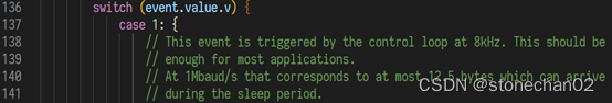
这里将这个注释稍微解释一下:
TIM8每3个半周期,也就是168MHz/(3500*3)=16KHz发出一次更新中断事件,然后触发中断处理函数“TIM8_UP_TIM13_IRQHandler()”。且上溢、下溢交替中断,但是仅仅在下溢时(此时计数方向转为向上),TIM8_UP_TIM13_IRQHandler()才会调用“control_loop_cb()”,所以“control_loop_cb()”执行频率降低为了8KHz,印证了上图注释中的解释。以上内容有不理解的,请参考:《ODrive0.5.5源码分析(2) 时钟和定时器.docx》
注释中第2段意思是:在8KHz的间隔周期下,最多能收多少个字节,也就是从理论上保证了缓冲不要溢出。
Ln400:
odrv.oscilloscope_.update();
详细了解代码要参考“MotorControl\oscilloscope.cpp”,从字面意思就可以看出:示波器。
示波器探测的值可以指向任何变量
![]()
每调用一次,就把我们要探测的信号值(比如我们想探测Ib)存入
![]()
OSCILLOSCOPE_SIZE目前被定义成:
![]()
前面已经分析过,调用频率大概8KHz,那么4096也就保存0.5s时间长度的连续数据了。
Ln403 ~ Ln408:
axis.min_endstop_.update();
axis.max_endstop_.update();
调用了“axis.min_endstop_”和“axis.max_endstop_”两个对象的“update()”。
其实就是两个开关按键的检测,涉及到防抖动等,可以设定高电平被认为按下还是低电平被认为按下。
最后设置结果参数是: “endstop_state_”
![]()
这个“min_endstop_”用在哪里呢?我们这里举例一个场景:
比如电机拉动一个“点胶喷嘴”做左右往复直线运动,点胶机要控制喷嘴分别在几个固定的位置处进行喷射,这些固定位置在工程上已经确定,比如:5cm、15cm等几个位置。现在问题来了:起始位置在哪?怎么让旋编计数值和物理位置0cm进行对应?
于是“endstop_”就发挥作用,它和“AXIS_STATE_HOMING”密切相关,具体参考代码:
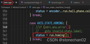
名字也取得很清晰“回家”,也就是回到物理原点,让电机转到“min_endstop_”被按住时,就认为“回家”了,也就是物理位置的0点。
程序中对“axis.max_endstop_”没有进行特别使用,是否homing成功也仅仅依靠了“axis.min_endstop_”:

也许我们自己可以扩展一下“max_endstop_”的功能,比如go-homing冲过了头,min和max两个开关都被按住了,那么物理位置应该是负数,直到max放开,min按住时才真正设置为0。 上面仅仅是我自己构思了一下而已。。。
Ln413:
bool checks_ok = axis.do_checks(timestamp);
下面贴出“do_checks()”代码,然后分析一下:
| 148 149 150 151 152 153 154 155 156 157 158 159 160 161 162 163 |
// @brief Do axis level checks and call subcomponent do_checks // Returns true if everything is ok. bool Axis::do_checks(uint32_t timestamp) { // Sub-components should use set_error which will propegate to this error_ motor_.effective_current_lim(); motor_.do_checks(timestamp); // Check for endstop presses if (min_endstop_.config_.enabled && min_endstop_.rose() && !(current_state_ == AXIS_STATE_HOMING)) { error_ |= ERROR_MIN_ENDSTOP_PRESSED; } else if (max_endstop_.config_.enabled && max_endstop_.rose() && !(current_state_ == AXIS_STATE_HOMING)) { error_ |= ERROR_MAX_ENDSTOP_PRESSED; } return check_for_errors(); } |
Ln152:
获取合适的电机的电流限制值,虽然我们设置了电机的限制电流:
axis.motor.config.current_lim
但是还要根据实际情况进行取舍:
比如通过增益参数等计算出来的:“axis_->motor_.max_allowed_current_”
因为电机发热了或者mos管温度过高后要进行电流限制
这几个综合考量,然后取最小的值作为电流限制值。
Ln153:
Drv8301控制方面的检测
电机温度和mos温度方面的检测
Ln156 ~ Ln160:
min_endstop和max_endstop 的开关状态是否合理
再回到函数“control_loop_cb()”中
Ln416:
bool watchdog_ok = axis.watchdog_check();
自己“定制的”看门狗是否出现没有及时喂狗错误
Ln427 ~ Ln428:
axis.motor_.fet_thermistor_.update();
axis.motor_.motor_thermistor_.update();
更新电机温度和mos管的温度。
Ln432:
axis.encoder_.update();
旋编相关的更新,这个函数的处理内容比较多,根据不同旋编类型读出当前的旋编值,然后计算速度,电角度等。
Ln438 ~ Ln456:
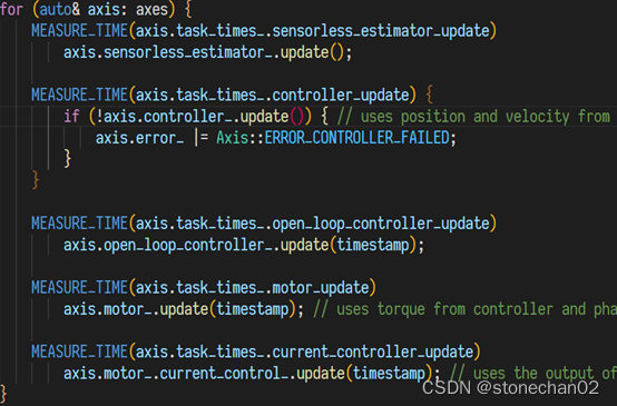
这一大块代码执行的时间较长,我们测量一下,下图红框中高电平为其执行时间:
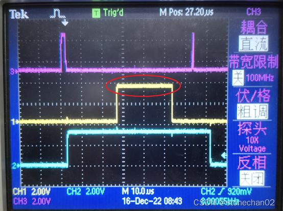
上面示波器的波形是什么意思,需要参考文章《ODrive0.5.5源码分析(2) 时钟和定时器》
下面更细一步分析:
Ln440:
axis.sensorless_estimator_.update();
无感控制观测器,实现了一个非线性观测器。
常见的无感控制观测器有:
龙伯格观测器+PLL
滑模观测器+PLL
扩展卡尔曼滤波观测器
非线性磁链观测器
本代码实现的是“非线性磁链观测器”
Ln443:
axis.controller_.update()
1)若步进激活,则根据步进的步数(steps),设置位置控制的位置控制值;
2)抗齿槽效应的校正;
3)根据输入模式的不同,比如速度爬坡、直通式、梯形控制等,分别处理,计算出位置或者速度或者力矩等的目标值。
4)最终都会归结到计算出力矩值“torque_output_”
Ln449:
axis.open_loop_controller_.update(timestamp);
计算出Idq,Vdq,根据phase速度估算出目前的phase位置,计算出转动的相角度的总距离
Ln452:
axis.motor_.update(timestamp);
计算出Vdq
Ln455:
axis.motor_.current_control_.update(timestamp);
将前面一系列步骤计算出来的最终结果更新到相应变量中:
Idq_setpoint_
Vdq_setpoint_
phase_
phase_vel_