作者|KIDGINBROOK
更新|潘丽晨
上节介绍所有节点执行了bootstrap网络连接的建立,接下来介绍下拓扑分析。
由于GPU机器架构是多种多样的,一台机器上可能有多个网卡,多个GPU卡,卡间连接也各不相同,因此需要对机器内设备连接拓扑进行分析,以使性能在各种拓扑结构下都尽可能好。
接着上回继续看initTransportsRank。
static ncclResult_t initTransportsRank(struct ncclComm* comm, ncclUniqueId* commId) {
  // We use 3 AllGathers
  // 1. { peerInfo, comm }
  // 2. ConnectTransport[nranks], ConnectValue[nranks]
  // 3. { nThreads, nrings, compCap, prev[MAXCHANNELS], next[MAXCHANNELS] }

  int rank = comm->rank;
  int nranks = comm->nRanks;
  uint64_t commHash = getHash(commId->internal, NCCL_UNIQUE_ID_BYTES);
  TRACE(NCCL_INIT, "comm %p, commHash %lx, rank %d nranks %d - BEGIN", comm, commHash, rank, nranks);
  NCCLCHECK(bootstrapInit(commId, rank, nranks, &comm->bootstrap));

  // AllGather1 - begin
  struct {
    struct ncclPeerInfo peerInfo;
    struct ncclComm* comm;
  } *allGather1Data;

  NCCLCHECK(ncclCalloc(&allGather1Data, nranks));
  allGather1Data[rank].comm = comm;
  struct ncclPeerInfo* myInfo = &allGather1Data[rank].peerInfo;
  NCCLCHECK(fillInfo(comm, myInfo, commHash));
  ...
}
创建nrank个allGather1Data,然后通过fillInfo 填充当前rank的peerInfo,ncclPeerInfo是rank的一些基本信息,比如rank号,在哪个机器的哪个进程等。
struct ncclPeerInfo {
  int rank;
  int cudaDev;
  int gdrSupport;
  uint64_t hostHash;
  uint64_t pidHash;
  dev_t shmDev;
  int64_t busId;
};

static ncclResult_t fillInfo(struct ncclComm* comm, struct ncclPeerInfo* info, uint64_t commHash) {
  info->rank = comm->rank;
  CUDACHECK(cudaGetDevice(&info->cudaDev));
  info->hostHash=getHostHash()+commHash;
  info->pidHash=getPidHash()+commHash;

  // Get the device MAJOR:MINOR of /dev/shm so we can use that
  // information to decide whether we can use SHM for inter-process
  // communication in a container environment
  struct stat statbuf;
  SYSCHECK(stat("/dev/shm", &statbuf), "stat");
  info->shmDev = statbuf.st_dev;

  info->busId = comm->busId;

  NCCLCHECK(ncclGpuGdrSupport(&info->gdrSupport));
  return ncclSuccess;
}
获取当前卡的rank,PCIe busId,/dev/shm的设备号,填充到ncclPeerInfo,然后通过ncclGpuGdrSupport查看是否支持gdr,rdma在通信前需要注册一段内存,使得网卡知道虚拟地址和物理地址的映射,但是如果每次通信都需要将data从显存拷贝到内存再通信的话效率就比较低。
而IB提供了peer memory的接口,使得ib网卡可以访问其他PCIe空间,nv基于peer memory实现了自己的驱动,使得rdma可以直接注册显存,这样通信就可以避免host和device的内存拷贝,IB可以直接dma显存,即gdr。
static ncclResult_t ncclGpuGdrSupport(int* gdrSupport) {
  int netDevs;
  NCCLCHECK(ncclNetDevices(&netDevs));
  *gdrSupport = 0;
  for (int dev=0; dev<netDevs; dev++) {
    // Find a net device which is GDR-capable
    ncclNetProperties_t props;
    NCCLCHECK(ncclNet->getProperties(dev, &props));
    if ((props.ptrSupport & NCCL_PTR_CUDA) == 0) continue;

    // Allocate memory on the GPU and try to register it on the NIC.
    void *lComm = NULL, *sComm = NULL, *rComm = NULL;
    ncclNetHandle_t handle;
    void* gpuPtr = NULL;
    void* mHandle = NULL;
    NCCLCHECK(ncclNetListen(dev, &handle, &lComm));
    NCCLCHECK(ncclNetConnect(dev, &handle, &sComm));
    NCCLCHECK(ncclNetAccept(lComm, &rComm));
    CUDACHECK(cudaMalloc(&gpuPtr, GPU_BUF_SIZE));
    ncclDebugNoWarn = NCCL_NET;
    if (ncclNetRegMr(sComm, gpuPtr, GPU_BUF_SIZE, NCCL_PTR_CUDA, &mHandle) == ncclSuccess) {
      NCCLCHECK(ncclNetDeregMr(sComm, mHandle));
      NCCLCHECK(ncclNetRegMr(rComm, gpuPtr, GPU_BUF_SIZE, NCCL_PTR_CUDA, &mHandle));
      NCCLCHECK(ncclNetDeregMr(rComm, mHandle));
      *gdrSupport = 1;
    }
    ncclDebugNoWarn = 0;
    CUDACHECK(cudaFree(gpuPtr));
    NCCLCHECK(ncclNetCloseRecv(rComm));
    NCCLCHECK(ncclNetCloseSend(sComm));
    NCCLCHECK(ncclNetCloseListen(lComm));
    break;
  }
  return ncclSuccess;
}
这里会遍历每一个网卡,获取网卡的信息,由第一节可以知道这里的ncclNet就是ncclNetIb。
ncclResult_t ncclIbGdrSupport(int ibDev) {
  static int moduleLoaded = -1;
  if (moduleLoaded == -1) {
    moduleLoaded = (access("/sys/kernel/mm/memory_peers/nv_mem/version", F_OK) == -1) ? 0 : 1;
  }
  if (moduleLoaded == 0) return ncclSystemError;
  return ncclSuccess;
}

ncclResult_t ncclIbGetProperties(int dev, ncclNetProperties_t* props) {
  props->name = ncclIbDevs[dev].devName;
  props->pciPath = ncclIbDevs[dev].pciPath;
  props->guid = ncclIbDevs[dev].guid;
  props->ptrSupport = NCCL_PTR_HOST;
  if (ncclIbGdrSupport(dev) != ncclSuccess) {
    INFO(NCCL_NET,"NET/IB : GPU Direct RDMA Disabled for HCA %d '%s' (no module)", dev, ncclIbDevs[dev].devName);
  } else {
    props->ptrSupport |= NCCL_PTR_CUDA;
  }
  props->speed = ncclIbDevs[dev].speed;
  props->port = ncclIbDevs[dev].port + ncclIbDevs[dev].realPort;
  props->maxComms = ncclIbDevs[dev].maxQp;
  return ncclSuccess;
}
这里主要是获取网卡名,PCIe路径,guid等信息,然后查看是否有/sys/kernel/mm/memory_peers/nv_mem/version判断是否安装了nv_peermem,即nv的驱动,如果安装了的话则设置props->ptrSupport |= NCCL_PTR_CUDA,表示可以注册显存。
然后尝试注册显存,如果可以注册则设置gdrSupport为1,这里其实会创建rdma连接,这个在后边会单独介绍,本次先略过。
static ncclResult_t initTransportsRank(struct ncclComm* comm, ncclUniqueId* commId) {
  ...
  NCCLCHECK(bootstrapAllGather(comm->bootstrap, allGather1Data, sizeof(*allGather1Data)));

  NCCLCHECK(ncclCalloc(&comm->peerInfo, nranks+1)); // Extra rank to represent CollNet root
  for (int i = 0; i < nranks; i++) {
    memcpy(comm->peerInfo+i, &allGather1Data[i].peerInfo, sizeof(struct ncclPeerInfo));
    if ((i != rank) && (comm->peerInfo[i].hostHash == myInfo->hostHash) && (comm->peerInfo[i].busId == myInfo->busId)) {
      WARN("Duplicate GPU detected : rank %d and rank %d both on CUDA device %x", rank, i, myInfo->busId);
      return ncclInvalidUsage;
    }
  }
  // AllGather1 data is used again below
  // AllGather1 - end

  // Topo detection / System graph creation
  NCCLCHECK(ncclTopoGetSystem(comm, &comm->topo));
  ...
}
然后bootstrapAllGather广播allGather1Data,将获取到的其他节点peerinfo拷贝到comm里。
在看具体拓扑分析流程之前先简单了解一下PCIe的一些概念,一个简单的PCIe系统示例如下。
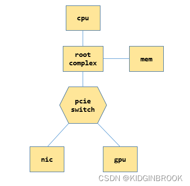
每个CPU都有自己的root complex,后简称为RC,RC会帮助cpu和其他部分通信,比如和内存,和PCIe系统,当cpu发送过来一个物理地址之后,如果这个地址是在PCIe空间,会被RC转换成PCIe请求进行通信。
switch的作用是扩展PCIe端口,下边可以连接设备或者其他switch,上游来的请求被被他转发,PCIe设备可以连在RC,也可以连在swtich,一个switch的内部如下所示。
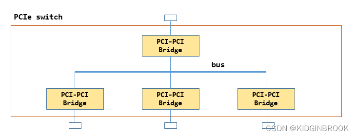
内部有一个PCIe总线 ,然后通过多个Bridge扩展出多个端口,其中上边的那个称为上游端口,其他的叫做下游端口。
前文有提到NCCL中很常用的一个变量名叫busId,比如gpu和ib网卡,注意区分NCCL里的busId并不是指的总线号,指的其实是定位一个PCIe设备用到的id,即BDF(bus + device + function),一个bus上有多个设备,一个设备有多个功能,因此通过BDF就可以定位一个设备,在机器启动完成PCIe的配置之后会将相关信息通过sysfs提供给用户,NCCL就是通过sysfs来完成拓扑检测的。
然后看下执行的ncclTopoGetSystem,这个函数就是本节的重点,会将当前rank的PCI树建立起来,分为两个步骤,先使用xml表示整个PCI树结构,然后基于xml转成ncclTopoNode,其中xml定义如下,一个ncclXmlNode表示了PCI树的一个节点。
struct ncclXmlNode {
  char name[MAX_STR_LEN];
  struct {
    char key[MAX_STR_LEN];
    char value[MAX_STR_LEN];
  } attrs[MAX_ATTR_COUNT+1]; // Need an extra one to consume extra params
  int nAttrs;
  int type;
  struct ncclXmlNode* parent;
  struct ncclXmlNode* subs[MAX_SUBS];
  int nSubs;
};

struct ncclXml {
  struct ncclXmlNode nodes[MAX_NODES];
  int maxIndex;
};
ncclXmlNode表示一个节点,记录了父节点和所有子节点,节点有name和attr,通过xmlSetAttr进行设置属性。
ncclXml中预分配了所有的node,maxIndex表示分配到了哪里,然后简单介绍下几个xml相关的api。
static ncclResult_t xmlAddNode(struct ncclXml* xml, struct ncclXmlNode* parent, const char* subName, struct ncclXmlNode** sub);xmlAddNode进行node的分配,表示在xml里新申请一个节点sub,sub的name设置为subName,父节点为parent。
static ncclResult_t xmlFindTagKv(struct ncclXml* xml, const char* tagName, struct ncclXmlNode** node, const char* attrName, const char* attrValue)xmlFindTagKv会遍历xml已分配的节点,找到节点名为tagName的节点n,然后判断节点n["attrName"]是否等于attrValue,如果相等,则设置node为n。
static ncclResult_t xmlGetAttrIndex(struct ncclXmlNode* node, const char* attrName, int* index)xmlGetAttrIndex会查看attrName是node的第几个属性。
然后开始看拓扑分析的过程。
ncclResult_t ncclTopoGetSystem(struct ncclComm* comm, struct ncclTopoSystem** system) {
  struct ncclXml* xml;
  NCCLCHECK(ncclCalloc(&xml, 1));
  char* xmlTopoFile = getenv("NCCL_TOPO_FILE");
  if (xmlTopoFile) {
    INFO(NCCL_ENV, "NCCL_TOPO_FILE set by environment to %s", xmlTopoFile);
    NCCLCHECK(ncclTopoGetXmlFromFile(xmlTopoFile, xml));
  }
  if (xml->maxIndex == 0) {
    // Create top tag
    struct ncclXmlNode* top;
    NCCLCHECK(xmlAddNode(xml, NULL, "system", &top));
    NCCLCHECK(xmlSetAttrInt(top, "version", NCCL_TOPO_XML_VERSION));
  }

  // Auto-detect GPUs if needed
  for (int r=0; r<comm->nRanks; r++) {
    if (comm->peerInfo[r].hostHash == comm->peerInfo[comm->rank].hostHash) {
      char busId[NVML_DEVICE_PCI_BUS_ID_BUFFER_SIZE];
      NCCLCHECK(int64ToBusId(comm->peerInfo[r].busId, busId));
      struct ncclXmlNode* node;
      NCCLCHECK(ncclTopoFillGpu(xml, busId, &node));
      if (node == NULL) continue;
      NCCLCHECK(xmlSetAttrInt(node, "rank", r));
      NCCLCHECK(xmlInitAttrInt(node, "gdr", comm->peerInfo[r].gdrSupport));
    }
  }
  ...
}
首先通过xmlAddNode创建根节点"system"(后续使用双引号表示xml树节点),并设置根节点属性"system" ["version"] = NCCL_TOPO_XML_VERSION,然后遍历每个rank的hosthash,如果相等的话说明在同一个机器,然后执行ncclTopoFillGpu,将gpu加入到xml树。
ncclResult_t ncclTopoFillGpu(struct ncclXml* xml, const char* busId, struct ncclXmlNode** gpuNode) {
  struct ncclXmlNode* node;
  NCCLCHECK(ncclTopoGetPciNode(xml, busId, &node));
  NCCLCHECK(ncclTopoGetXmlFromSys(node, xml));
  ...
}
ncclResult_t ncclTopoGetPciNode(struct ncclXml* xml, const char* busId, struct ncclXmlNode** pciNode) {
NCCLCHECK(xmlFindTagKv(xml, "pci", pciNode, "busid", busId));
if (*pciNode == NULL) {
NCCLCHECK(xmlAddNode(xml, NULL, "pci", pciNode));
}
NCCLCHECK(xmlSetAttr(*pciNode, "busid", busId));
return ncclSuccess;
}通过ncclTopoGetPciNode获取xml中的有没有创建当前卡的xml node,此时没有,所以就新建一个xml node叫做"pci",表示当前gpu卡,设置"pci"["busid"]=busd。
然后执行ncclTopoGetXmlFromSys,这个函数主要逻辑就是在sysfs中获取gpu节点到cpu的路径,通过这个路径转成xml树,并读取该路径下相关属性设置到xml里。
ncclResult_t ncclTopoGetXmlFromSys(struct ncclXmlNode* pciNode, struct ncclXml* xml) {
  // Fill info, then parent
  const char* busId;
  NCCLCHECK(xmlGetAttr(pciNode, "busid", &busId));
  char* path = NULL;
  int index;
  NCCLCHECK(xmlGetAttrIndex(pciNode, "class", &index));
  if (index == -1) {
    if (path == NULL) NCCLCHECK(getPciPath(busId, &path));
    NCCLCHECK(ncclTopoSetAttrFromSys(pciNode, path, "class", "class"));
  }
  NCCLCHECK(xmlGetAttrIndex(pciNode, "link_speed", &index));
  if (index == -1) {
    if (path == NULL) NCCLCHECK(getPciPath(busId, &path));
    char deviceSpeedStr[MAX_STR_LEN];
    float deviceSpeed;
    NCCLCHECK(ncclTopoGetStrFromSys(path, "max_link_speed", deviceSpeedStr));
    sscanf(deviceSpeedStr, "%f GT/s", &deviceSpeed);
    char portSpeedStr[MAX_STR_LEN];
    float portSpeed;
    NCCLCHECK(ncclTopoGetStrFromSys(path, "../max_link_speed", portSpeedStr));
    sscanf(portSpeedStr, "%f GT/s", &portSpeed);
    NCCLCHECK(xmlSetAttr(pciNode, "link_speed", portSpeed < deviceSpeed ? portSpeedStr : deviceSpeedStr));
  }
  NCCLCHECK(xmlGetAttrIndex(pciNode, "link_width", &index));
  if (index == -1) {
    if (path == NULL) NCCLCHECK(getPciPath(busId, &path));
    char strValue[MAX_STR_LEN];
    NCCLCHECK(ncclTopoGetStrFromSys(path, "max_link_width", strValue));
    int deviceWidth = strtol(strValue, NULL, 0);
    NCCLCHECK(ncclTopoGetStrFromSys(path, "../max_link_width", strValue));
    int portWidth = strtol(strValue, NULL, 0);
    NCCLCHECK(xmlSetAttrInt(pciNode, "link_width", std::min(deviceWidth,portWidth)));
  }
  ...
}
首先设置pciNode的各种属性,通过getPciPath获取busId对应的sysfs路径path,其实这个路径就是PCI树中根到叶结点的路径。
static ncclResult_t getPciPath(const char* busId, char** path) {
  char busPath[] = "/sys/class/pci_bus/0000:00/../../0000:00:00.0";
  memcpylower(busPath+sizeof("/sys/class/pci_bus/")-1, busId, BUSID_REDUCED_SIZE-1);
  memcpylower(busPath+sizeof("/sys/class/pci_bus/0000:00/../../")-1, busId, BUSID_SIZE-1);
  *path = realpath(busPath, NULL);
  if (*path == NULL) {
    WARN("Could not find real path of %s", busPath);
    return ncclSystemError;
  }
  return ncclSuccess;
}
举个例子比如path是 /sys/devices/pci0000:10/0000:10:00.0/0000:11:00.0/0000:12:00.0/0000:13:00.0/0000
:14:00.0/0000:15:00.0/0000:16:00.0/0000:17:00.0,其中GPU的busId是0000:17:00.0,那么这个path对应下图,注意,下图略去了15:00.0对应的switch。
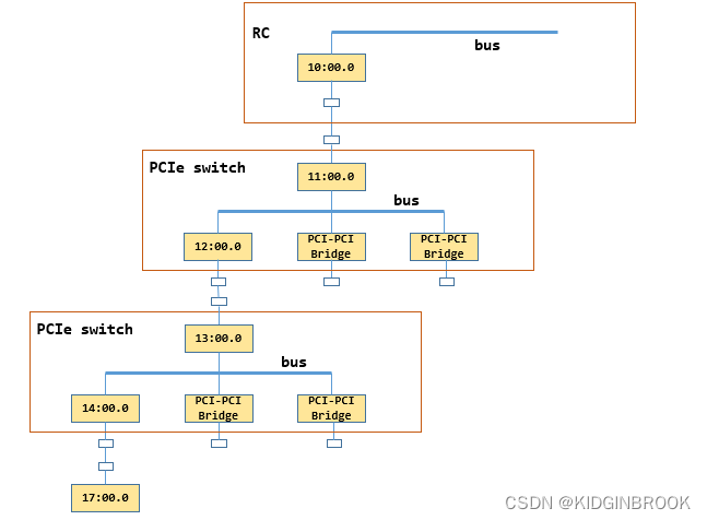
然后读取path下的属性,获取class(PCI设备类型),link_speed,link_width等设置到xml pciNode中,ncclTopoGetStrFromSys其实就是读取path下的内核文件保存到strValue。
ncclResult_t ncclTopoGetStrFromSys(const char* path, const char* fileName, char* strValue) {
  char filePath[PATH_MAX];
  sprintf(filePath, "%s/%s", path, fileName);
  int offset = 0;
  FILE* file;
  if ((file = fopen(filePath, "r")) != NULL) {
    while (feof(file) == 0 && ferror(file) == 0 && offset < MAX_STR_LEN) {
      int len = fread(strValue+offset, 1, MAX_STR_LEN-offset, file);
      offset += len;
    }
    fclose(file);
  }
  if (offset == 0) {
    strValue[0] = '\0';
    INFO(NCCL_GRAPH, "Topology detection : could not read %s, ignoring", filePath);
  } else {
    strValue[offset-1] = '\0';
  }
  return ncclSuccess;
}
ncclResult_t ncclTopoGetXmlFromSys(struct ncclXmlNode* pciNode, struct ncclXml* xml) {
// Fill info, then parent
...
struct ncclXmlNode* parent = pciNode->parent;
if (parent == NULL) {
if (path == NULL) NCCLCHECK(getPciPath(busId, &path));
// Save that for later in case next step is a CPU
char numaIdStr[MAX_STR_LEN];
NCCLCHECK(ncclTopoGetStrFromSys(path, "numa_node", numaIdStr));
// Go up one level in the PCI tree. Rewind two "/" and follow the upper PCI
// switch, or stop if we reach a CPU root complex.
int slashCount = 0;
int parentOffset;
for (parentOffset = strlen(path)-1; parentOffset>0; parentOffset--) {
if (path[parentOffset] == '/') {
slashCount++;
path[parentOffset] = '\0';
int start = parentOffset - 1;
while (start>0 && path[start] != '/') start--;
// Check whether the parent path looks like "BBBB:BB:DD.F" or not.
if (checkBDFFormat(path+start+1) == 0) {
// This a CPU root complex. Create a CPU tag and stop there.
struct ncclXmlNode* topNode;
NCCLCHECK(xmlFindTag(xml, "system", &topNode));
NCCLCHECK(xmlGetSubKv(topNode, "cpu", &parent, "numaid", numaIdStr));
if (parent == NULL) {
NCCLCHECK(xmlAddNode(xml, topNode, "cpu", &parent));
NCCLCHECK(xmlSetAttr(parent, "numaid", numaIdStr));
}
} else if (slashCount == 2) {
// Continue on the upper PCI switch
for (int i = strlen(path)-1; i>0; i--) {
if (path[i] == '/') {
NCCLCHECK(xmlFindTagKv(xml, "pci", &parent, "busid", path+i+1));
if (parent == NULL) {
NCCLCHECK(xmlAddNode(xml, NULL, "pci", &parent));
NCCLCHECK(xmlSetAttr(parent, "busid", path+i+1));
}
break;
}
}
}
}
if (parent) break;
}
pciNode->parent = parent;
parent->subs[parent->nSubs++] = pciNode;
}
if (strcmp(parent->name, "pci") == 0) {
NCCLCHECK(ncclTopoGetXmlFromSys(parent, xml));
} else if (strcmp(parent->name, "cpu") == 0) {
NCCLCHECK(ncclTopoGetXmlFromCpu(parent, xml));
}
free(path);
return ncclSuccess;
}然后从pciNode开始往上跳,因为一个switch的上游端口和下游端口分别对应了一个bridge,NCCL使用上游端口bridge的busid表示这个switch,因此这里要向上跳两次再建立一个xml node表示这个switch,往上找到一个PCI设备就将slashCount加一。
当slashCount==2就找到了一个switch上游端口,这个时候创建一个新的xml pci节点parent表示当前switch,然后将当前节点pciNode链接到parent,此时parent仍然是xml pci节点。
因此,继续递归执行ncclTopoGetXmlFromSys,直到遇到RC,此时给"system"创建一个子节点"cpu",停止递归,然后执行ncclTopoGetXmlFromCpu,设置"cpu"的各种属性,比如arch(比如x86还是arm),affinity(该cpu的numa都有哪些cpu core),numaid等。
到这里ncclTopoGetXmlFromSys就执行结束了,接着看ncclTopoFillGpu。
ncclResult_t ncclTopoFillGpu(struct ncclXml* xml, const char* busId, struct ncclXmlNode** gpuNode) {
  ...
  NCCLCHECK(wrapNvmlSymbols());
  NCCLCHECK(wrapNvmlInit());
  nvmlDevice_t nvmlDev;
  if (wrapNvmlDeviceGetHandleByPciBusId(busId, &nvmlDev) != ncclSuccess) nvmlDev = NULL;
  NCCLCHECK(ncclTopoGetXmlFromGpu(node, nvmlDev, xml, gpuNode));
  return ncclSuccess;
}
然后通过wrapNvmlSymbols加载动态库libnvidia-ml.so.1,用来获取gpu的相关信息。
ncclResult_t ncclTopoGetXmlFromGpu(struct ncclXmlNode* pciNode, nvmlDevice_t nvmlDev, struct ncclXml* xml, struct ncclXmlNode** gpuNodeRet) {
  struct ncclXmlNode* gpuNode = NULL;
  NCCLCHECK(xmlGetSub(pciNode, "gpu", &gpuNode));
  if (gpuNode == NULL) NCCLCHECK(xmlAddNode(xml, pciNode, "gpu", &gpuNode));

  int index = -1;

  int dev = -1;
  NCCLCHECK(xmlGetAttrIndex(gpuNode, "dev", &index));
  if (index == -1) {
    if (nvmlDev == NULL) {
      WARN("No NVML, trying to use CUDA instead");
      const char* busId;
      NCCLCHECK(xmlGetAttr(pciNode, "busid", &busId));
      if (busId == NULL || cudaDeviceGetByPCIBusId(&dev, busId) != cudaSuccess) dev = -1;
    } else {
      NCCLCHECK(wrapNvmlDeviceGetIndex(nvmlDev, (unsigned int*)&dev));
    }
    NCCLCHECK(xmlSetAttrInt(gpuNode, "dev", dev));
  }
  NCCLCHECK(xmlGetAttrInt(gpuNode, "dev", &dev));
  if (dev == -1) { *gpuNodeRet = NULL; return ncclSuccess; }

  NCCLCHECK(xmlGetAttrIndex(gpuNode, "sm", &index));
  if (index == -1) {
    int cudaMajor, cudaMinor;
    if (nvmlDev == NULL) {
      cudaDeviceProp devProp;
      CUDACHECK(cudaGetDeviceProperties(&devProp, dev));
      cudaMajor = devProp.major; cudaMinor = devProp.minor;
    } else {
      NCCLCHECK(wrapNvmlDeviceGetCudaComputeCapability(nvmlDev, &cudaMajor, &cudaMinor));
    }
    NCCLCHECK(xmlSetAttrInt(gpuNode, "sm", cudaMajor*10+cudaMinor));
  }
  int sm;
  NCCLCHECK(xmlGetAttrInt(gpuNode, "sm", &sm));

  struct ncclXmlNode* nvlNode = NULL;
  NCCLCHECK(xmlGetSub(pciNode, "nvlink", &nvlNode));
  if (nvlNode == NULL) {
    // NVML NVLink detection
    int maxNvLinks = (sm < 60) ? 0 : (sm < 70) ? 4 : (sm < 80) ? 6 : 12;

    if (maxNvLinks > 0 && nvmlDev == NULL) {
      WARN("No NVML device handle. Skipping nvlink detection.\n");
      maxNvLinks = 0;
    }

    for (int l=0; l<maxNvLinks; ++l) {
      // Check whether we can use this NVLink for P2P
      unsigned canP2P;
      if ((wrapNvmlDeviceGetNvLinkCapability(nvmlDev, l, NVML_NVLINK_CAP_P2P_SUPPORTED, &canP2P) != ncclSuccess) || !canP2P) continue;

      // Make sure the Nvlink is up. The previous call should have trained the link.
      nvmlEnableState_t isActive;
      if ((wrapNvmlDeviceGetNvLinkState(nvmlDev, l, &isActive) != ncclSuccess) || (isActive != NVML_FEATURE_ENABLED)) continue;

      // Try to figure out what's on the other side of the NVLink
      nvmlPciInfo_t remoteProc;
      if (wrapNvmlDeviceGetNvLinkRemotePciInfo(nvmlDev, l, &remoteProc) != ncclSuccess) continue;

      // Make a lower case copy of the bus ID for calling ncclDeviceType
      // PCI system path is in lower case
      char* p = remoteProc.busId;
      char lowerId[NVML_DEVICE_PCI_BUS_ID_BUFFER_SIZE];
      for (int c=0; c<NVML_DEVICE_PCI_BUS_ID_BUFFER_SIZE; c++) {
        lowerId[c] = tolower(p[c]);
        if (p[c] == 0) break;
      }

      NCCLCHECK(xmlGetSubKv(gpuNode, "nvlink", &nvlNode, "target", lowerId));
      if (nvlNode == NULL) {
        NCCLCHECK(xmlAddNode(xml, gpuNode, "nvlink", &nvlNode));
        NCCLCHECK(xmlSetAttr(nvlNode, "target", lowerId));
        NCCLCHECK(xmlSetAttrInt(nvlNode, "count", 1));
      } else {
        int count;
        NCCLCHECK(xmlGetAttrInt(nvlNode, "count", &count));
        NCCLCHECK(xmlSetAttrInt(nvlNode, "count", count+1));
      }
    }
  }
  // Fill target classes
  for (int s=0; s<gpuNode->nSubs; s++) {
    struct ncclXmlNode* sub = gpuNode->subs[s];
    if (strcmp(sub->name, "nvlink") != 0) continue;
    int index;
    NCCLCHECK(xmlGetAttrIndex(sub, "tclass", &index));
    if (index == -1) {
      const char* busId;
      NCCLCHECK(xmlGetAttr(sub, "target", &busId));
      if (strcmp(busId, "fffffff:ffff:ff") == 0) {
        // Remote NVLink device is not visible inside this VM. Assume NVSwitch.
        NCCLCHECK(xmlSetAttr(sub, "tclass", "0x068000"));
      } else {
        char* path;
        NCCLCHECK(getPciPath(busId, &path));
        NCCLCHECK(ncclTopoSetAttrFromSys(sub, path, "class", "tclass"));
      }
    }
  }
  *gpuNodeRet = gpuNode;
  return ncclSuccess;
}
首先在xml gpu节点"pci"下创建节点"gpu",然后设置"gpu"节点的属性,比如dev,计算能力sm,然后开始查询nvlink相关信息,遍历所有可能的nvlink,通过nvmlDeviceGetNvLinkCapability查询nvlink信息。
如果这个nvlink被启用,那么在"gpu"节点下新建一个"nvlink"节点,设置"target"属性表示nvlink对端的PCIe busId,将"target"相同的"nvlink"节点表示为一个,用"count"表示起止点之间有多少条nvlink,然后设置属性"tclass"表示"target"是什么类型的PCI设备。
到这里ncclTopoFillGpu就执行结束了,此时xml如下所示,图里只展示了一张网卡的情况,其中"gpu"和他的父节点其实都是指的同一个gpu。
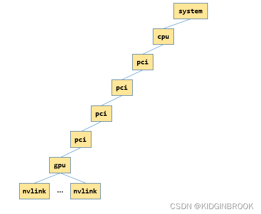
然后回到ncclTopoGetSystem,会设置"gpu"的rank和gdr属性。
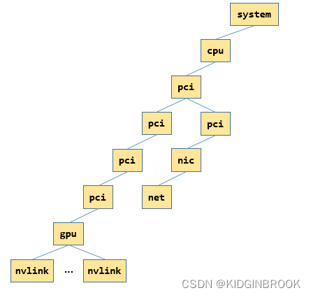
然后是对于所有的网卡,类似上述gpu的过程,通过ncclTopoGetXmlFromSys建立xml树,如下所示,只展示一张网卡的情况,其中"net","nic"和"nic"的父节点都表示同一张网卡。
<system version="1">
  <cpu numaid="0" affinity="00000000,0000000f,ffff0000,00000000,000fffff" arch="x86_64" vendor="GenuineIntel" familyid="6" modelid="85">
    <pci busid="0000:11:00.0" class="0x060400" link_speed="8 GT/s" link_width="16">
      <pci busid="0000:13:00.0" class="0x060400" link_speed="8 GT/s" link_width="16">
        <pci busid="0000:15:00.0" class="0x060400" link_speed="8 GT/s" link_width="16">
          <pci busid="0000:17:00.0" class="0x030200" link_speed="16 GT/s" link_width="16">
            <gpu dev="0" sm="80" rank="0" gdr="1">
              <nvlink target="0000:e7:00.0" count="2" tclass="0x068000"/>
              <nvlink target="0000:e4:00.0" count="2" tclass="0x068000"/>
              <nvlink target="0000:e6:00.0" count="2" tclass="0x068000"/>
              <nvlink target="0000:e9:00.0" count="2" tclass="0x068000"/>
              <nvlink target="0000:e5:00.0" count="2" tclass="0x068000"/>
              <nvlink target="0000:e8:00.0" count="2" tclass="0x068000"/>
            </gpu>
          </pci>
        </pci>
      </pci>
      <pci busid="0000:1c:00.0" class="0x020000" link_speed="8 GT/s" link_width="16">
        <nic>
          <net name="mlx5_0" dev="0" speed="100000" port="1" guid="0x82d0c0003f6ceb8" maxconn="262144" gdr="1"/>
        </nic>
      </pci>
    </pci>
  </cpu>
</system>
总结一下,本节主要介绍了NCCL拓扑分析的过程,通过sysfs将gpu和网卡对应的pci树结构建立出来了xml树。
(原文:
https://blog.csdn.net/KIDGIN7439/article/details/126990961)
其他人都在看
欢迎Star、试用OneFlow: github.com/Oneflow-Inc/oneflow/