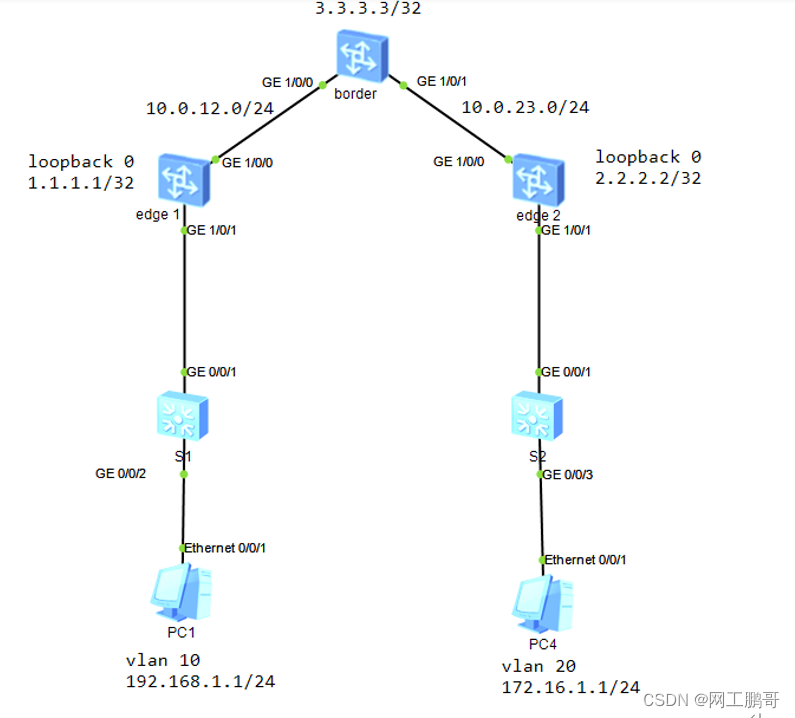
网络拓扑:
实验需求:
使用evpn在edge1和edge2之间建立vxlan隧道,edge设备作为终端的网关。实现PC1和PC2之间能够互相通信。Border作为edge1的evpn的反射器,负责evpn路由的传递和数据的转发。
实验步骤:
步骤1:配置underlay 网络及连接终端的交换设备
S1和S2的vlan基本配置
S1:
vlan   10

interface GigabitEthernet0/0/1

 port link-type trunk

 port trunk allow-pass vlan 10

interface GigabitEthernet0/0/2

 port link-type access

 port default vlan 10
S2:
vlan batch 20

interface GigabitEthernet0/0/1

 port link-type trunk

 port trunk allow-pass vlan 20

interface GigabitEthernet0/0/3

 port link-type access

 port default vlan 20
Boder:
ospf 1

 area 0.0.0.0

  network 3.3.3.3 0.0.0.0

  network 10.0.12.0 0.0.0.255

  network 10.0.23.0 0.0.0.255
edge1:
ospf 1

 area 0.0.0.0

  network 1.1.1.1 0.0.0.0

  network 10.0.12.0 0.0.0.255
edge2:
ospf 1

 area 0.0.0.0

  network 2.2.2.2 0.0.0.0

  network 10.0.23.0 0.0.0.255
步骤2:配置edge节点的BD域,将vni绑定到BD域中。
Edge1:
bridge-domain 10

 vxlan vni 10
edge2:
bridge-domain 20

 vxlan vni 20
步骤3:edge配置子接口、不同的子接口绑定到不同的BD域
Edge1:
interface GE1/0/1

 undo shutdown //默认情况下物理接口为down

interface GE1/0/1.10 mode l2 //配置子接口为2层子接口

 encapsulation dot1q vid 10 //配置子接口能够处理vlan10的数据

 bridge-domain 10//将子接口绑定BD域
edge2:
interface GE1/0/1

 undo shutdown

interface GE1/0/1.20 mode l2

 encapsulation dot1q vid 20

 bridge-domain 20
步骤5:配置EVPN的邻居关系
Border:
bgp 100

 peer 1.1.1.1 as-number 100

 peer 1.1.1.1 connect-interface LoopBack0

 peer 2.2.2.2 as-number 100

 peer 2.2.2.2 connect-interface LoopBack0
l2vpn-family evpn
undo policy vpn-target //关闭RT检查,由于border 设备并不创建vpn实例,只需要传递evpn的路由信息,需要关闭RT检查,否则将不接收edge设备传递过来的路由信息
peer 1.1.1.1 enable
peer 1.1.1.1 advertise irb
peer 1.1.1.1 reflect-client
peer 2.2.2.2 enable
peer 2.2.2.2 advertise irb
peer 2.2.2.2 reflect-clientedge1:
bgp 100

 peer 3.3.3.3 as-number 100

 peer 3.3.3.3 connect-interface LoopBack0


l2vpn-family evpn

  policy vpn-target

  peer 3.3.3.3 enable
bgp 100
peer 3.3.3.3 as-number 100
peer 3.3.3.3 connect-interface LoopBack0
l2vpn-family evpn
policy vpn-target
peer 3.3.3.3 enableedge2:
bgp 100

 peer 3.3.3.3 as-number 100

 peer 3.3.3.3 connect-interface LoopBack0


l2vpn-family evpn

  policy vpn-target

  peer 3.3.3.3 enable
peer 3.3.3.3 advertise irb查看bgp的evpn邻居关系:

步骤6:配置BD域的Evpn实例,配置RD和RT值
Edge1:
bridge-domain 10

 vxlan vni 10 //二层VNI

 evpn

  route-distinguisher 10:10

  vpn-target 10:10 export-extcommunity //RT 10:10用于两端mac route(type2路由的发布和接收)

  vpn-target 11:1 export-extcommunity //RT11:1与三层vpn实例的入方向RT对应,主要用于生成vpn实例的全局主机路由

  vpn-target 10:10 import-extcommunity
edge2:
bridge-domain 20

 vxlan vni 20

 evpn

  route-distinguisher 10:11

  vpn-target 10:10 export-extcommunity

  vpn-target 11:1 export-extcommunity

  vpn-target 10:10 import-extcommunity
步骤7:配置ip vpn实例
Edge1:
i
p vpn-instance 1

 ipv4-family

  route-distinguisher 10:10

  vpn-target 11:1 evpn //与BD域的evpn实例出方向RT一致,当设备收到type 2的路由时,如果RT与ip vpn实例的入方向RT一致,则收集其中的arp信息,生成主机路由,并且放在vpn实例路由表中

 vxlan vni 1000// 配置三层VNI,用于指定设备收到流量后将数据发往哪一个vpn实例,然后查表转发,主要用于业务隔离
edge2:
ip vpn-instance 1

 ipv4-family

  route-distinguisher 10:10

  vpn-target 11:1 evpn

 vxlan vni 1000// 配置三层VNI,用于指定设备收到流量后将数据发往哪一个vpn实例,然后查表转发
步骤8:创建VBDIF接口,作为终端设备的网关
Edge1:
interface Vbdif10

 ip binding vpn-instance 1 //绑定到ip vpn实例1中

 ip address 192.168.1.254 255.255.255.0

 vxlan anycast-gateway enable //配置此接口为vxlan的多播网关,仅学习主机端的arp信息,不学习网络端的arp信息

 arp collect host enable//收集主机的arp信息,即主机上线后,发送的arp信息,将被构建成type2的路由发布给对端
edge2:
interface Vbdif20

 ip binding vpn-instance 1

 ip address 172.16.1.254 255.255.255.0

 vxlan anycast-gateway enable

 arp collect host enable
步骤9:配置NVE接口,使用evpn自动创建vxlan隧道
Edge1:
interface Nve1

 source 1.1.1.1

 vni 10 head-end peer-list protocol bgp
edge2:
interface Nve1

 source 2.2.2.2

 vni 20 head-end peer-list protocol bgp
查看vxlan隧道建立情况

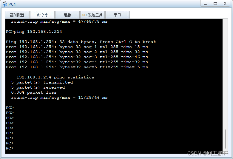
步骤10:使用主机访问网关,产生type2的主机路由信息
查看edge1的bgp evpn 路由表

此时PC2也访问网关,再次查看bgp的evpn路由表

查看PC2的arp 路由信息详细信息
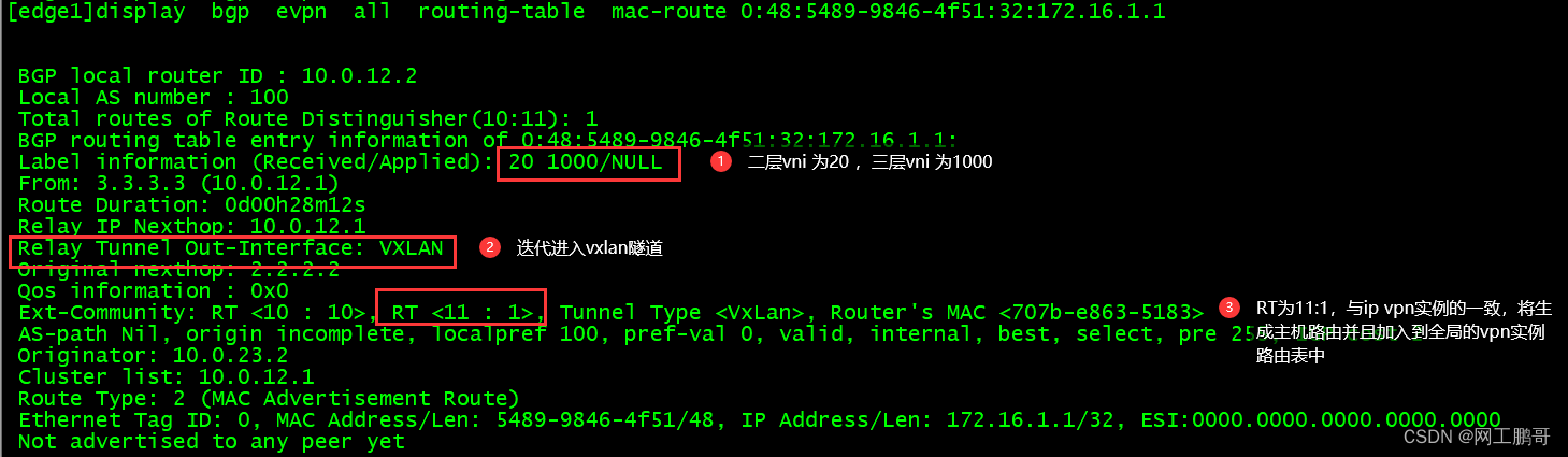
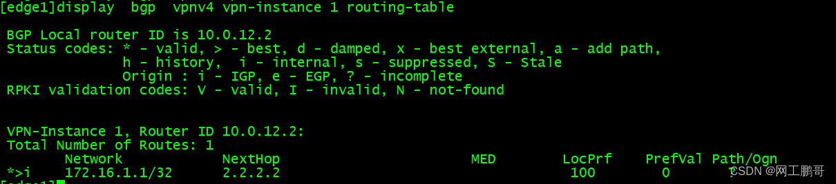
查看edge1的bgp vpn实例1的路由表,可以发现生成了172.16.1.1/32的路由信息
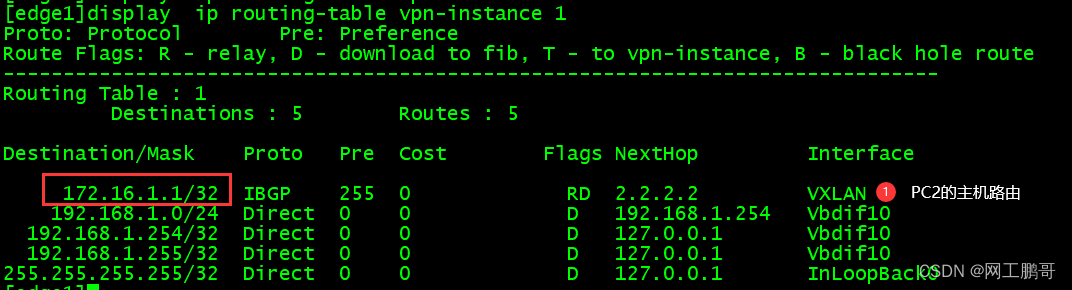
查看全局的vpn实例路由表,当网关收到去往172.16.1.1/32的目的ip时,将迭代到vxlan隧道
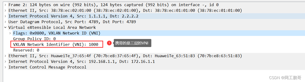
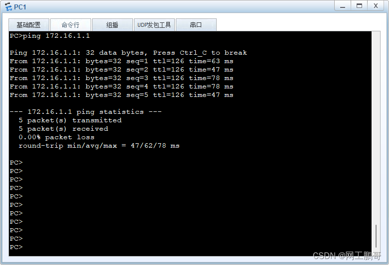
PC1访问PC2。(测试之前先使用PC访问网关,确保网关上有两个PC的type2 arp信息。
查看抓包结果