完成以下实验的所有要求:
此实验有6个网段,按照要求进行子网划分。
eg:
192.168.1.0/24
192.168.1.00000000
借3个位,可划分8个子网。
192.168.1.000 00000 /27 ----骨干链路
1、192.168.1.000 000 00 192.168.1.0 /30
2、192.168.1.000 001 00 192.168.1.4 /30
3、192.168.1.000 010 00 192.168.1.8 /30
4、192.168.1.000 011 00 192.168.1.12/30
5、192.168.1.000 100 00 192.168.1.16/30
6、192.168.1.000 101 00 192.168.1.20/30
7、192.168.1.000 110 00 192.168.1.24/30
8、192.168.1.000 111 00 192.168.1.28/30
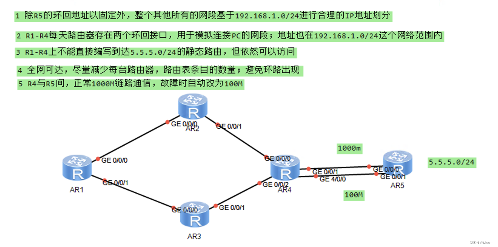
由题意2,R1-R4每个路由器需两个环回接口。
R1:192.168.1.001 0 0000 192.168.1.32/27 ----汇总后的子网
192.168.1.001 0 0000 192.168.1.32/28
192.168.1.001 1 0000 192.168.1.48/28
R2:192.168.1.010 0 0000 192.168.1.64/27 ----汇总后的子网
192.168.1.010 0 0000 192.168.1.64/28
192.168.1.010 1 0000 192.168.1.80/28
R3:192.168.1.011 0 0000 192.168.1.96/27 ----汇总后的子网
192.168.1.011 0 0000 192.168.1.96/28
192.168.1.011 1 0000 192.168.1.112/28
R4:192.168.1.100 0 0000 192.168.1.128/27 ----汇总后的子网
192.168.1.100 0 0000 192.168.1.128/28
192.168.1.100 1 0000 192.168.1.144/28
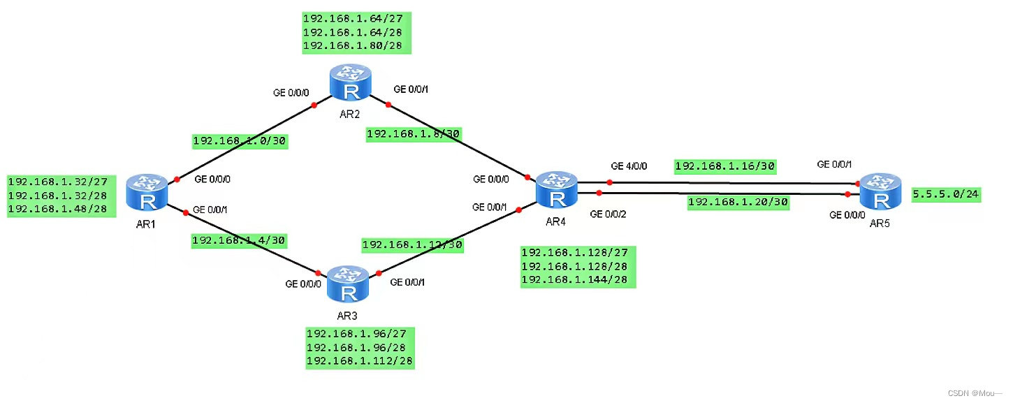
分配好的ip地址如下:

实验配置
首先将每个路由器改名为r1-r5。
R1:
<Huawei>system-view
[Huawei]sysname R1
[R1]
(同理将其他四个路由改为R2-R5)
再给每个路由器分配ip地址
R1的静态路由配置:
[R1]int g0/0/0
[R1-GigabitEthernet0/0/0]ip add 192.168.1.1 30
[R1-GigabitEthernet0/0/0]int g0/0/1
[R1-GigabitEthernet0/0/1]ip add 192.168.1.5 30
[R1-GigabitEthernet0/0/1]int lo 0
[R1-LoopBack0]ip add 192.168.1.33 28
[R1-LoopBack0]int lo 1
[R1-LoopBack1]ip add 192.168.1.49 28
R2的静态路由配置:
[R2]int g0/0/0
[R2-GigabitEthernet0/0/0]ip ad 192.168.1.2 30
[R2-GigabitEthernet0/0/0]int g0/0/1
[R2-GigabitEthernet0/0/1]ip ad 192.168.1.9 30
[R2-GigabitEthernet0/0/1]int lo 0
[R2-LoopBack0]ip ad 192.168.1.65 28
[R2-LoopBack0]int lo1
[R2-LoopBack1]ip ad 192.168.1.81 28
R3的静态路由配置:
[R3]int g0/0/0
[R3-GigabitEthernet0/0/0]ip ad 192.168.1.6 30
[R3-GigabitEthernet0/0/0]int g0/0/1
[R3-GigabitEthernet0/0/1]ip ad 192.168.1.13 30
[R3-GigabitEthernet0/0/1]int lo0
[R3-LoopBack0]ip ad 192.168.1.97 28
[R3-LoopBack0]int lo1
[R3-LoopBack1]ip ad 192.168.1.113 28
R4的静态路由配置:
[R4]int g0/0/0
[R4-GigabitEthernet0/0/0]ip ad 192.168.1.10 30
[R4-GigabitEthernet0/0/0]int g0/0/1
[R4-GigabitEthernet0/0/1]ip ad 192.168.1.14 30
[R4-GigabitEthernet0/0/1]int g4/0/0
[R4-GigabitEthernet4/0/0]ip ad 192.168.1.17 30
[R4-GigabitEthernet4/0/0]int g0/0/2
[R4-GigabitEthernet0/0/2]ip ad 192.168.1.21 30
[R4-GigabitEthernet0/0/2]int lo0
[R4-LoopBack0]ip ad 192.168.1.129 28
[R4-LoopBack0]int lo1
[R4-LoopBack1]ip ad 192.168.1.145 28
R5的静态路由配置:
[R5]int g0/0/1
[R5-GigabitEthernet0/0/1]ip add 192.168.1.18 30
[R5-GigabitEthernet0/0/1]int g0/0/0
[R5-GigabitEthernet0/0/0]ip add 192.168.1.22 30
[R5-GigabitEthernet0/0/0]int lo0
[R5-LoopBack0]ip ad 5.5.5.5 24
(可以使用display ip interface brief来检查一下所分配的ip信息)
然后实现全网可达,对每个路由进行路由配置
R1路由配置:
[R1]ip route-static 192.168.1.64 27 192.168.1.2
[R1]ip route-static 192.168.1.96 27 192.168.1.6
[R1]ip route-static 192.168.1.8 30 192.168.1.2
[R1]ip route-static 192.168.1.12 30 192.168.1.6
[R1]ip route-static 192.168.1.128 27 192.168.1.2
[R1]ip route-static 192.168.1.128 27 192.168.1.6
[R1]ip route-static 192.168.1.16 30 192.168.1.2
[R1]ip route-static 192.168.1.16 30 192.168.1.6
R2路由配置:
[R2]ip route-static 192.168.1.32 27 192.168.1.1
[R2]ip route-static 192.168.1.128 27 192.168.1.10
[R2]ip route-static 192.168.1.96 27 192.168.1.1
[R2]ip route-static 192.168.1.96 27 192.168.1.10
[R2]ip route-static 192.168.1.16 30 192.168.1.10
[R2]ip route-static 192.168.1.4 30 192.168.1.1
[R2]ip route-static 192.168.1.12 30 192.168.1.10
R3路由配置:
[R3]ip route-static 192.168.1.32 27 192.168.1.5
[R3]ip route-static 192.168.1.0 30 192.168.1.5
[R3]ip route-static 192.168.1.128 27 192.168.1.14
[R3]ip route-static 192.168.1.8 30 192.168.1.14
[R3]ip route-static 192.168.1.16 30 192.168.1.14
[R3]ip route-static 192.168.1.64 27 192.168.1.5
[R3]ip route-static 192.168.1.64 27 192.168.1.14
R4路由配置:
[R4]ip route-static 192.168.1.96 27 192.168.1.13
[R4]ip route-static 192.168.1.4 30 192.168.1.13
[R4]ip route-static 192.168.1.64 27 192.168.1.9
[R4]ip route-static 192.168.1.0 30 192.168.1.9
[R4]ip route-static 192.168.1.32 27 192.168.1.9
[R4]ip route-static 192.168.1.32 27 192.168.1.13
R5路由配置:
[R5]ip route-static 192.168.1.128 27 192.168.1.17
[R5]ip route-static 192.168.1.8 30 192.168.1.17
[R5]ip route-static 192.168.1.12 30 192.168.1.17
[R5]ip route-static 192.168.1.64 27 192.168.1.17
[R5]ip route-static 192.168.1.0 30 192.168.1.17
[R5]ip route-static 192.168.1.32 27 192.168.1.17
[R5]ip route-static 192.168.1.96 27 192.168.1.17
[R5]ip route-static 192.168.1.4 30 192.168.1.17
最后检查一下各路由之间是否Ping通!
由于R1-R4不能直接编写到5.5.5.0/24的静态路由,也就无法访问5.5.5.0网段,即ping到5.5.5.5是ping不过去的。若要让其能访问,要给各个路由写上缺省地址。
R1的缺省地址:
[R1]ip route-static 0.0.0.0 0.0.0.0 192.168.1.2
[R1]ip route-static 0.0.0.0 0.0.0.0 192.168.1.6
R2的缺省地址:
[R2]ip route-static 0.0.0.0 0.0.0.0 192.168.1.10
R3的缺省地址:
[R3]ip route-static 0.0.0.0 0.0.0.0 192.168.1.14
R4的缺省地址:
[R4]ip route-static 0.0.0.0 0.0.0.0 192.168.1.18
此时每个路由再去ping5.5.5.5就可以ping通。
为了避免环路出现,还应该在每个路由添加空接口
R1
[R1]ip route-static 192.168.1.32 27 NULL 0
R2
[R2]ip route-static 192.168.1.64 27 NULL 0
R3
[R3]ip route-static 192.168.1.96 27 NULL 0
R4
[R4]ip route-static 192.168.1.128 27 NULL 0
要使R4与R5间,正常1000M链路通信,故障时自动改为100M,就要用到浮动静态路由,根据优先级的数值越小,优先级越高,将100M链路的优先级调整为61即可。
查看一下R5路由,修改100M链路的优先级
[R5]ip route-static 192.16.1.0 255.255.255.252 192.168.1.21 preference 61
[R5]ip route-static 192.168.1.4 255.255.255.252 192.168.1.21 preference 61
[R5]ip route-static 192.168.1.8 255.255.255.252 192.168.1.21 preference 61
[R5]ip route-static 192.168.1.12 255.255.255.252 192.168.1.21 preference 61
[R5]ip route-static 192.168.1.32 255.255.255.252 192.168.1.21 preference 61
[R5]ip route-static 192.168.1.64 255.255.255.252 192.168.1.21 preference 61
[R5]ip route-static 192.168.1.96 255.255.255.252 192.168.1.21 preference 61
[R5]ip route-static 192.168.1.128 255.255.255.252 192.168.1.21 preference 61

接下来验证是否在故障时使用的是100M的链路,首先需将1000M链路断开
[R4]int g4/0/0
[R4-GigabitEthernet4/0/0]shutdown
[R5]int g0/0/1
[R5-GigabitEthernet0/0/1]shutdown
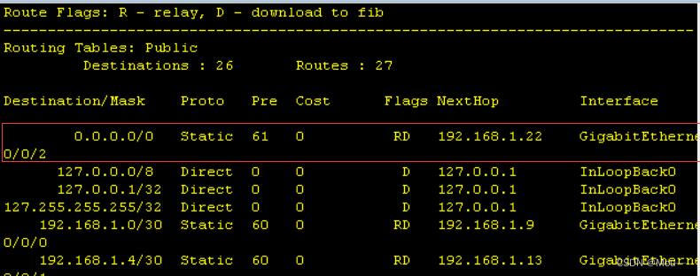
断开之后去R4查看此时的路由表,发现100M的接口已经在路由表上
最后还可再用路由ping 5.5.5.5,检查是否ping通即可。