目录
第六章 VLAN特性与配置
实验 6-3 VLAN间通信
学习目的
·掌握多臂路由的配置方法
·掌握单臂路由的配置方法
·掌握VLAN间通信的配置方法
·掌握VLAN聚合的配置方法
拓扑图
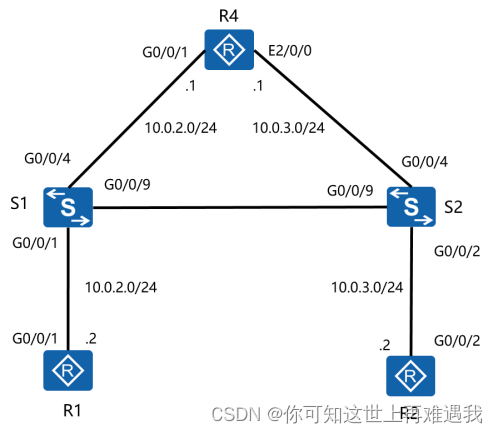
图6-3 VLAN间通信
场景
你是公司的网络管理员。现在公司网络是由二台交换机和一台路由器组成的以太网环境。图中R1和R2代表公司不同部门的PC,分别加入了二个不同的VLAN。现在需要你实现R1和R2之间的通信。公司最初使用的是多臂路由,后来为了节省成本使用单臂路由。
再后来,因为网络架构的变化,流量更多是在VLAN间传输,所以采用了多层交换。最后,因为为了方便网络管理采用VLAN聚合的技术。
学习任务
步骤一.基础配置与IP编址
给所有设备配置IP地址和掩码。
<huawei>system-view
Enter system view, return user view with Ctrl+Z.
[huawei]sysname R1
[R1]interface GigabitEthernet 0/0/1
[R1-GigabitEthernet0/0/1]ip address 10.0.2.2 24
[R1-GigabitEthernet0/0/1]quit
<huawei>system-view
Enter system view, return user view with Ctrl+Z.
[huawei]sysname R2
[R2]interface GigabitEthernet 0/0/2
[R2-GigabitEthernet0/0/2]ip address 10.0.3.2 24
[R2-GigabitEthernet0/0/2]quit
<Huawei>system-view
Enter system view, return user view with Ctrl+Z.
[Huawei]sysname S1
<Huawei>system-view
Enter system view, return user view with Ctrl+Z.
[Huawei]sysname S2
<huawei>system-view
Enter system view, return user view with Ctrl+Z.
[huawei]sysname R4
[R4]interface GigabitEthernet 0/0/1
[R4-GigabitEthernet0/0/1]ip address 10.0.2.1 24
[R4-GigabitEthernet0/0/1]quit
[R4]interface Ethernet2/0/0
[R4-Ethernet2/0/0]ip address 10.0.3.1 24
[R4-Ethernet2/0/0]quit
使用ping命令测试R1与R4接口G0/0/1的地址的连通性。
[R1]ping -c 1 10.0.2.1
PING 10.0.2.1: 56 data bytes, press CTRL_C to break
Reply from 10.0.2.1: bytes=56 Sequence=1 ttl=255 time=4 ms
--- 10.0.2.1 ping statistics ---
1 packet(s) transmitted
1 packet(s) received
0.00% packet loss
round-trip min/avg/max = 4/4/4 ms
使用ping命令测试R2和R4直连接口的连通性。
[R2]ping -c 1 10.0.3.1
PING 10.0.3.1: 56 data bytes, press CTRL_C to break
Reply from 10.0.3.1: bytes=56 Sequence=1 ttl=255 time=3 ms
--- 10.0.3.1 ping statistics ---
1 packet(s) transmitted
1 packet(s) received
0.00% packet loss
round-trip min/avg/max = 3/3/3 ms
步骤二.多臂路由
R1和R2分别处于不同的VLAN中。
R1的网关使用R4的G0/0/1接口地址,R2的网关使用R4的E2/0/0接口地址。
由R4的多个接口提供VLAN间通信的服务就叫做多臂路由。
在交换机S1和S2上创建VLAN2和VLAN3。
[S1]vlan batch 2 3
Info: This operation may take a few seconds. Please wait for a moment...done.
[S2]vlan batch 2 3
Info: This operation may take a few seconds. Please wait for a moment...done.
将R1加入VLAN2,R2加入VLAN3,R4的G0/0/1加入VLAN2,E2/0/0加入VLAN3。
[S1]interface GigabitEthernet 0/0/1
[S1-GigabitEthernet0/0/1]port link-type access
[S1-GigabitEthernet0/0/1]port default vlan 2
[S1-GigabitEthernet0/0/1]quit
[S1]interface GigabitEthernet 0/0/4
[S1-GigabitEthernet0/0/4]port link-type access
[S1-GigabitEthernet0/0/4]port default vlan 2
[S1-GigabitEthernet0/0/4]quit
[S2]interface GigabitEthernet 0/0/2
[S2-GigabitEthernet0/0/2]port link-type access
[S2-GigabitEthernet0/0/2]port default vlan 3
[S2-GigabitEthernet0/0/2]quit
[S2]interface GigabitEthernet 0/0/4
[S2-GigabitEthernet0/0/4]port link-type access
[S2-GigabitEthernet0/0/4]port default vlan 3
[S2-GigabitEthernet0/0/4]quit
在R1和R2上配置网关,分别使用所在VLAN的R4接口地址。
[R1]ip route-static 0.0.0.0 0 10.0.2.1
[R2]ip route-static 0.0.0.0 0 10.0.3.1
使用命令display vlan查看并确认配置。
[S1]display vlan 2
----------------------------------------------------------------------------
U: Up; D: Down; TG: Tagged; UT: Untagged;
MP: Vlan-mapping; ST: Vlan-stacking;
#: ProtocolTransparent-vlan; *: Management-vlan;
----------------------------------------------------------------------------
VID Type Ports
----------------------------------------------------------------------------
2 common UT:GE0/0/1(U) GE0/0/4(U)
TG:GE0/0/9(U) GE0/0/10(U)
VID Status Property MAC-LRN Statistics Description
----------------------------------------------------------------------------
2 enable default enable disable VLAN 0002
[S2]display vlan 3
----------------------------------------------------------------------------
U: Up; D: Down; TG: Tagged; UT: Untagged;
MP: Vlan-mapping; ST: Vlan-stacking;
#: ProtocolTransparent-vlan; *: Management-vlan;
----------------------------------------------------------------------------
VID Type Ports
----------------------------------------------------------------------------
3 common UT:GE0/0/2(U) GE0/0/4(U)
TG:GE0/0/9(U) GE0/0/10(U)
VID Status Property MAC-LRN Statistics Description
----------------------------------------------------------------------------
3 enable default enable disable VLAN 0003
测试R1和R2之间的连通性。
[R1]ping -c 1 10.0.3.2
PING 10.0.3.2: 56 data bytes, press CTRL_C to break
Reply from 10.0.3.2: bytes=56 Sequence=1 ttl=254 time=3 ms
--- 10.0.3.2 ping statistics ---
1 packet(s) transmitted
1 packet(s) received
0.00% packet loss
round-trip min/avg/max = 3/3/3 ms
[R2]ping -c 1 10.0.2.2
PING 10.0.2.2: 56 data bytes, press CTRL_C to break
Reply from 10.0.2.2: bytes=56 Sequence=1 ttl=254 time=3 ms
--- 10.0.2.2 ping statistics ---
1 packet(s) transmitted
1 packet(s) received
0.00% packet loss
round-trip min/avg/max = 3/3/3 ms
步骤三.单臂路由
在R4的一个物理接口上创建二个子接口,VLAN间的通讯通过对应的子接口完成。
这种方法叫做单臂路由。
关闭S2的G0/0/4接口。
[S2]interface GigabitEthernet 0/0/4
[S2-GigabitEthernet0/0/4]shutdown
[S2-GigabitEthernet0/0/4]quit
将S1和S2的G0/0/9接口加入VLAN 3。
[S2]interface GigabitEthernet 0/0/9
[S2-GigabitEthernet0/0/9]port link-type access
[S2-GigabitEthernet0/0/9]port default vlan 3
[S2-GigabitEthernet0/0/9]quit
[S1]interface GigabitEthernet 0/0/9
[S1-GigabitEthernet0/0/9]port link-type access
[S1-GigabitEthernet0/0/9]port default vlan 3
[S1-GigabitEthernet0/0/9]quit
将S1的G0/0/4接口模式改为Trunk模式,并允许VLAN2和VLAN3通过。
[S1]interface GigabitEthernet 0/0/4
[S1-GigabitEthernet0/0/4]port default vlan 1
[S1-GigabitEthernet0/0/4]port link-type trunk
[S1-GigabitEthernet0/0/4]port trunk allow-pass vlan 2 3
[S1-GigabitEthernet0/0/4]quit
在R4上为G0/0/1接口创建两个子接口。同时子接口上配置IP地址,并封装相应vid。
[R4]inter GigabitEthernet 0/0/1.2
[R4-GigabitEthernet0/0/1.2]dot1q termination vid 2
[R4-GigabitEthernet0/0/1.2]arp broadcast enable
[R4-GigabitEthernet0/0/1.2]ip address 10.0.20.1 24
[R4-GigabitEthernet0/0/1.2]quit
[R4]interface GigabitEthernet 0/0/1.3
[R4-GigabitEthernet0/0/1.3]dot1q termination vid 3
[R4-GigabitEthernet0/0/1.3]arp broadcast enable
[R4-GigabitEthernet0/0/1.3]ip address 10.0.30.1 24
[R4-GigabitEthernet0/0/1.3]quit
使用display ip interface brief命令查看R4上子接口配置信息。
[R4]display ip interface brief
*down: administratively down
^down: standby
(l): loopback
(s): spoofing
(E): E-Trunk down
The number of interface that is UP in Physical is 7
The number of interface that is DOWN in Physical is 6
The number of interface that is UP in Protocol is 5
The number of interface that is DOWN in Protocol is 8
Interface IP Address/Mask Physical Protocol
Cellular0/0/0 unassigned down down
Cellular0/0/1 unassigned down down
Ethernet2/0/0 10.0.3.1/24 down down
Ethernet2/0/1 unassigned down down
GigabitEthernet0/0/0 unassigned up down
GigabitEthernet0/0/1 10.0.2.1/24 up up
GigabitEthernet0/0/1.2 10.0.20.1/24 up up
GigabitEthernet0/0/1.3 10.0.30.1/24 up up
GigabitEthernet0/0/2 unassigned down down
GigabitEthernet0/0/3 unassigned up down
NULL0 unassigned up up(s)
Serial1/0/0 unassigned up up
Serial1/0/1 unassigned down down
更改R1和R2的IP地址和网关。
[R1]interface GigabitEthernet 0/0/1
[R1-GigabitEthernet0/0/1]ip address 10.0.20.2 24
[R1-GigabitEthernet0/0/1]quit
[R1]undo ip route-static 0.0.0.0 0 10.0.2.1
[R1]ip route-static 0.0.0.0 0 10.0.20.1
[R2]interface GigabitEthernet 0/0/2
[R2-GigabitEthernet0/0/2]ip address 10.0.30.2 24
[R2-GigabitEthernet0/0/2]quit
[R2]undo ip route-static 0.0.0.0 0 10.0.3.1
[R2]ip route-static 0.0.0.0 0 10.0.30.1
测试R1和R2之间的连通性。
[R1]ping -c 1 10.0.30.2
PING 10.0.30.2: 56 data bytes, press CTRL_C to break
Reply from 10.0.30.2: bytes=56 Sequence=1 ttl=254 time=3 ms
--- 10.0.30.2 ping statistics ---
1 packet(s) transmitted
1 packet(s) received
0.00% packet loss
round-trip min/avg/max = 3/3/3 ms
从ping命令的输出结果可知,VLAN 2的计算机和VLAN 3的计算机成功通信。
这种方案相对于多臂路由方案可以节省企业购买路由器接口的资金。
但相对的,单臂路由由于所有数据都在同一个接口上传输,随着VLAN数量的增加将会增大这条链路的带宽压力。同时这条链路也成为了企业网络的单点故障,一旦出现问题则整个网络都无法通信。
步骤四.三层交换
三层交换指的是不需要路由器帮助,每个VLAN都有一个Vlanif接口充当路由器接口的角色来实现不同VLAN间通信的方法。
关闭S1的G0/0/4接口。
[S1]interface GigabitEthernet 0/0/4
[S1-GigabitEthernet0/0/4]shutdown
[S1-GigabitEthernet0/0/4]quit
更改S1的G0/0/9接口和S2的G0/0/9接口的模式为Trunk模式,允许VLAN2和VLAN3通过。
[S1]interface GigabitEthernet 0/0/9
[S1-GigabitEthernet0/0/9]port default vlan 1
[S1-GigabitEthernet0/0/9]port link-type trunk
[S1-GigabitEthernet0/0/9]port trunk allow-pass vlan 2 3
[S1-GigabitEthernet0/0/9]quit
[S2]interface GigabitEthernet 0/0/9
[S2-GigabitEthernet0/0/9]port default vlan 1
[S2-GigabitEthernet0/0/9]port link-type trunk
[S2-GigabitEthernet0/0/9]port trunk allow-pass vlan 2 3
[S2-GigabitEthernet0/0/9]quit
在S1上创建Vlanif 2接口和Vlanif 3接口,并配置IP地址。
[S1]interface Vlanif 2
[S1-Vlanif2]ip address 10.0.20.1 24
[S1-Vlanif2]quit
[S1]inter Vlanif 3
[S1-Vlanif3]ip address 10.0.30.1 24
[S1-Vlanif3]quit
测试R1和R2之间的连通性。
[R1]ping -c 1 10.0.30.2
PING 10.0.30.2: 56 data bytes, press CTRL_C to break
Reply from 10.0.30.2: bytes=56 Sequence=1 ttl=254 time=2 ms
--- 10.0.30.2 ping statistics ---
1 packet(s) transmitted
1 packet(s) received
0.00% packet loss
round-trip min/avg/max = 2/2/2 ms
从ping命令的输出结果可知,VLAN2 和VLAN 3的计算机通过交换机S1的二个Vlanif接口实现了三层数据通信。
相比单臂路由方案,三层交换更具有扩展性,即使VLAN增加也不会对其性能造成很大影响。
在VLAN间通信占企业大部分流量的网络中能够很好的承担服务压力。
步骤五.VLAN聚合
VLAN聚合和三层交换类似,都可以实现交换机上不同VLAN之间的通信。相比三层交换的方案它能将所有VLAN都放置在同一个网段中,达到减少IP网段使用和统一网关配置的效果。
在S1和S2上创建VLAN 10、20、100。
[S1]vlan batch 10 20 100
Info: This operation may take a few seconds. Please wait for a moment...done.
[S2]vlan batch 10 20 100
Info: This operation may take a few seconds. Please wait for a moment...done.
配置S1和S2的G0/0/9接口允许VLAN10、20通过。
[S1]interface GigabitEthernet 0/0/9
[S1-GigabitEthernet0/0/9]port trunk allow-pass vlan 10 20
[S1-GigabitEthernet0/0/9]quit
[S2]interface GigabitEthernet 0/0/9
[S2-GigabitEthernet0/0/9]port trunk allow-pass vlan 10 20
[S2-GigabitEthernet0/0/9]quit
将S1的G0/0/1接口和S2的G0/0/2接口分别加入VLAN 10和VLAN 20。
[S1]interface GigabitEthernet 0/0/1
[S1-GigabitEthernet0/0/1]port default vlan 10
[S1-GigabitEthernet0/0/1]quit
[S2]interface GigabitEthernet 0/0/2
[S2-GigabitEthernet0/0/1]port default vlan 20
[S2-GigabitEthernet0/0/1]quit
将VLAN100配置为Super-VLAN,并将VLAN 10和VLAN 20作为Sub-VLAN加入VLAN 100。
[S1]vlan 100
[S1-vlan100]aggregate-vlan
[S1-vlan100]access-vlan 10 20
[S1-Vlan100]quit
配置VLAN 100的Vlanif接口,启用ARP Proxy功能。
[S1]interface Vlanif 100
[S1-Vlanif100]ip address 10.0.100.1 24
[S1-Vlanif100]arp-proxy inter-sub-vlan-proxy enable
[S1-Vlanif100]quit
更改R1和R2的IP地址,使其与Vlanif 100接口在同一个网段。并且将网关配置为Vlanif 100的接口地址。
[R1]interface GigabitEthernet 0/0/1
[R1-GigabitEthernet0/0/1]ip address 10.0.100.2 24
[R1-GigabitEthernet0/0/1]quit
[R1]undo ip route-static 0.0.0.0 0 10.0.20.1
[R1]ip route-static 0.0.0.0 0 10.0.100.1
[R2]interface GigabitEthernet 0/0/2
[R2-GigabitEthernet0/0/2]ip address 10.0.100.3 24
[R2-GigabitEthernet0/0/2]quit
[R2]undo ip route-static 0.0.0.0 0 10.0.30.1
[R2]ip route-static 0.0.0.0 0 10.0.100.1
测试R1、R2和S1的Vlanif100接口之间的连通性。
[R1]ping -c 1 10.0.100.1
PING 10.0.100.1: 56 data bytes, press CTRL_C to break
Reply from 10.0.100.1: bytes=56 Sequence=1 ttl=254 time=3 ms
--- 10.0.100.1 ping statistics ---
1 packet(s) transmitted
1 packet(s) received
0.00% packet loss
round-trip min/avg/max = 3/3/3 ms
[R1]ping -c 1 10.0.100.3
PING 10.0.100.3: 56 data bytes, press CTRL_C to break
Reply from 10.0.100.3: bytes=56 Sequence=1 ttl=254 time=2 ms
--- 10.0.100.3 ping statistics ---
1 packet(s) transmitted
1 packet(s) received
0.00% packet loss
round-trip min/avg/max = 2/2/2 ms
[R2]pin -c 1 10.0.100.1
PING 10.0.100.1: 56 data bytes, press CTRL_C to break
Reply from 10.0.100.1: bytes=56 Sequence=1 ttl=254 time=3 ms
--- 10.0.100.1 ping statistics ---
1 packet(s) transmitted
1 packet(s) received
0.00% packet loss
round-trip min/avg/max = 3/3/3 ms
从ping命令的输出结果可知,R1、R2和S1的Vlanif 100接口可以互相通信。相比三层交换方案,VLAN聚合方案能够实现不同VLAN都使用相同的网关通信的功能,有效的减少IP地址的浪费和提高管理效率。但相对的,相同网段的计算机之间互访都依靠同一个Vlanif接口,也使这个接口的压力增大。
附加实验: 思考并验证
多臂路由、单臂路由、VLAN间通信和VLAN聚合这四种方案各自的特点、优缺点和适用场景是怎么样的?
最终设备配置
[S1]display current-configuration
!Software Version V200R008C00SPC500
#
sysname S1
#
vlan batch 2 to 3 10 20 100
#
diffserv domain default
#
drop-profile default
#
vlan 100
aggregate-vlan
access-vlan 10 20
#
aaa
authentication-scheme default
authorization-scheme default
accounting-scheme default
domain default
domain default_admin
local-user admin password irreversible-cipher %^%#tK;J&jw0HG8<9-"zX!kHwzXRNjuXn96[vN47F$*L~pXcROEP3!>c)NV+:`i;%^%#
local-user admin service-type http
#
interface Vlanif1
#
interface Vlanif2
ip address 10.0.20.1 255.255.255.0
#
interface Vlanif3
ip address 10.0.30.1 255.255.255.0
#
interface Vlanif100
ip address 10.0.100.1 255.255.255.0
arp-proxy inter-sub-vlan-proxy enable
#
interface MEth0/0/1
#
interface GigabitEthernet0/0/1
port link-type access
port default vlan 10
#
interface GigabitEthernet0/0/2
#
interface GigabitEthernet0/0/3
#
interface GigabitEthernet0/0/4
shutdown
port link-type trunk
port trunk allow-pass vlan 2 to 3
#
interface GigabitEthernet0/0/5
#
interface GigabitEthernet0/0/6
#
interface GigabitEthernet0/0/7
#
interface GigabitEthernet0/0/8
#
interface GigabitEthernet0/0/9
port link-type trunk
port trunk allow-pass vlan 2 to 3 10 20
#
interface GigabitEthernet0/0/10
#
interface NULL0
#
user-interface con 0
authentication-mode password
set authentication password cipher $1a$fcjGHMtb0U$^GKZ+`,g@DfG$:T/P,R~iJ&')|!O":$b4)0*~&c-$
idle-timeout 0 0
user-interface vty 0 4
user-interface vty 16 20
#
return
[S2]display current-configuration
!Software Version V200R008C00SPC500
#
sysname S2
#
vlan batch 2 to 3 10 20 100
#
diffserv domain default
#
drop-profile default
#
aaa
authentication-scheme default
authorization-scheme default
accounting-scheme default
domain default
domain default_admin
local-user admin password irreversible-cipher %^%#gI/bO8qF$HkpAPUgNd'GiYR4TC!>EK#oG("Wl4_#$G*OKo-'7*R[h3+49<Z2%^%#
local-user admin service-type http
#
interface Vlanif1
#
interface MEth0/0/1
#
interface GigabitEthernet0/0/1
#
interface GigabitEthernet0/0/2
port link-type access
port default vlan 20
#
interface GigabitEthernet0/0/3
#
interface GigabitEthernet0/0/4
shutdown
port link-type access
port default vlan 3
#
interface GigabitEthernet0/0/5
#
interface GigabitEthernet0/0/6
#
interface GigabitEthernet0/0/7
#
interface GigabitEthernet0/0/8
#
interface GigabitEthernet0/0/9
port link-type trunk
port trunk allow-pass vlan 2 to 3 10 20
#
interface GigabitEthernet0/0/10
#
user-interface con 0
authentication-mode password
set authentication password cipher $1a$5"l`L7$/5T$,KFQ9dEy~'IggWOa7V(C+9fQOd*M;U6q,.Sl1y'H$
idle-timeout 0 0
user-interface vty 0 4
user-interface vty 16 20
#
return
[R4]display current-configuration
[V200R007C00SPC600]
#
sysname R4
#
board add 0/1 2SA
board add 0/2 2FE
#
drop illegal-mac alarm
#
pki realm default
enrollment self-signed
#
ssl policy default_policy type server
pki-realm default
#
aaa
authentication-scheme default
authorization-scheme default
accounting-scheme default
domain default
domain default_admin
local-user admin password irreversible-cipher %^%#`S|f)zA5xQeP^7UA/d/LH:}m3<KxR6fH,g5a%d)'zc,T/&qu:XPCg7))ihy5%^%#
local-user admin privilege level 15
local-user admin service-type terminal http
#
firewall zone Local
priority 64
#
interface Ethernet2/0/0
ip address 10.0.3.1 255.255.255.0
#
interface Ethernet2/0/1
#
interface Serial1/0/0
link-protocol ppp
#
interface Serial1/0/1
link-protocol ppp
#
interface GigabitEthernet0/0/0
#
interface GigabitEthernet0/0/1
ip address 10.0.2.1 255.255.255.0
#
interface GigabitEthernet0/0/1.2
dot1q termination vid 2
ip address 10.0.20.1 255.255.255.0
#
interface GigabitEthernet0/0/1.3
dot1q termination vid 3
ip address 10.0.30.1 255.255.255.0
#
interface GigabitEthernet0/0/2
#
interface GigabitEthernet0/0/3
description VirtualPort
#
interface Cellular0/0/0
#
interface Cellular0/0/1
#
interface NULL0
#
snmp-agent local-engineid 800007DB03D0D04B03D43B
#
http secure-server ssl-policy default_policy
http server enable
http secure-server enable
#
user-interface con 0
authentication-mode aaa
idle-timeout 0 0
user-interface vty 0
authentication-mode aaa
user privilege level 15
user-interface vty 1 4
#
wlan ac
#
voice
#
diagnose
#
ops
#
autostart
#
return