1.设备的支持
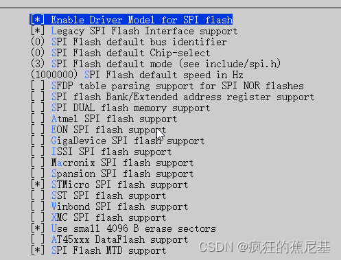
在使用新的spi-nor的设备时,首先要知道,你的设备的厂商和ID,这样才能做具体的menuconfig设备支持.具体的menuconfig配置路径如下,找到对应的设备厂商的SPI FLASH 开启即可。
 Location:                                                                                                                                                                                                                          │
  │    -> Device Drivers                                                                                                                                                                                                                │
  │       -> MTD Support                                                                                                                                                                                                                 │
  │          -> SPI Flash Support
如果是国产设备,或者其他厂商设备,没有在menuconfig里进行支持的话, 可以手动进行设备的添加。
添加位置位于:uboot\drivers\mtd\spi 路径下,spi-nor-ids.c 文件中, 所有与spi 设备相关的设备信息都在这里进行描述。不同的厂商用不同的宏定义开启,所以要在menuconfig 进行配置。
const struct flash_info spi_nor_ids[] = {


#ifdef CONFIG_SPI_FLASH_ATMEL		/* ATMEL */
	/* Atmel -- some are (confusingly) marketed as "DataFlash" */
	{

     INFO("at26df321",	0x1f4700, 0, 64 * 1024, 64, SECT_4K) },
	{

     INFO("at25df321a",	0x1f4701, 0, 64 * 1024, 64, SECT_4K) },

	{

     INFO("at45db011d",	0x1f2200, 0, 64 * 1024,   4, SECT_4K) },
	{

     INFO("at45db021d",	0x1f2300, 0, 64 * 1024,   8, SECT_4K) },
	{

     INFO("at45db041d",	0x1f2400, 0, 64 * 1024,   8, SECT_4K) },
	{

     INFO("at45db081d",	0x1f2500, 0, 64 * 1024,  16, SECT_4K) },
	{

     INFO("at45db161d",	0x1f2600, 0, 64 * 1024,  32, SECT_4K) },
	{

     INFO("at45db321d",	0x1f2700, 0, 64 * 1024,  64, SECT_4K) },
	{

     INFO("at45db641d",	0x1f2800, 0, 64 * 1024, 128, SECT_4K) },
	{

     INFO("at26df081a", 	0x1f4501, 0, 64 * 1024,  16, SECT_4K) },
#endif
#ifdef CONFIG_SPI_FLASH_STMICRO		/* STMICRO */
	/* Micron */
	{

     INFO("n25q016a",	 0x20bb15, 0, 64 * 1024,   32, SECT_4K | SPI_NOR_QUAD_READ) },
	{

     INFO("n25q032",	 0x20ba16, 0, 64 * 1024,   64, SPI_NOR_QUAD_READ) },
	{

     INFO("n25q032a",	0x20bb16, 0, 64 * 1024,   64, SPI_NOR_QUAD_READ) },
	{

     INFO("n25q064",     0x20ba17, 0, 64 * 1024,  128, SECT_4K | SPI_NOR_QUAD_READ) },
	{

     INFO("n25q064a",    0x20bb17, 0, 64 * 1024,  128, SECT_4K | SPI_NOR_QUAD_READ) },
	{

     INFO("n25q128a11",  0x20bb18, 0, 64 * 1024,  256, SECT_4K | SPI_NOR_QUAD_READ) },
	{

     INFO("n25q128a13",  0x20ba18, 0, 64 * 1024,  256, SECT_4K | SPI_NOR_QUAD_READ) },
	{

     INFO("n25q256a",    0x20ba19, 0, 64 * 1024,  512, SECT_4K | SPI_NOR_DUAL_READ | SPI_NOR_QUAD_READ | SPI_NOR_4B_OPCODES) },
	{

     INFO("n25q256ax1",  0x20bb19, 0, 64 * 1024,  512, SECT_4K | SPI_NOR_QUAD_READ ) },
	{

     INFO("n25q512a",    0x20bb20, 0, 64 * 1024, 1024, SECT_4K | USE_FSR | SPI_NOR_QUAD_READ | SPI_NOR_4B_OPCODES) },
	{

     INFO("n25q512ax3",  0x20ba20, 0, 64 * 1024, 1024, SECT_4K | USE_FSR | SPI_NOR_QUAD_READ | SPI_NOR_4B_OPCODES) },
	{

     INFO("n25q00",      0x20ba21, 0, 64 * 1024, 2048, SECT_4K | USE_FSR | SPI_NOR_QUAD_READ | NO_CHIP_ERASE) },
	{

     INFO("n25q00a",     0x20bb21, 0, 64 * 1024, 2048, SECT_4K | USE_FSR | SPI_NOR_QUAD_READ | NO_CHIP_ERASE) },
	{

     INFO("mt25qu02g",   0x20bb22, 0, 64 * 1024, 4096, SECT_4K | USE_FSR | SPI_NOR_QUAD_READ | NO_CHIP_ERASE) },

	{

     INFO("SM25QH256M",  0x206019, 0, 64 * 1024,  512, SECT_4K | SPI_NOR_DUAL_READ | SPI_NOR_QUAD_READ | SPI_NOR_4B_OPCODES) },


#endif
	{

    ......}//还有很多
}
SPI FLASH ids 设备信息描述
要分清设备具体配置那些信息,除了要了解用户手册中设备的属性,还要了解代码中,如何定义一个设备的属性。我们先看INFO,这个宏的定义:
#define INFO(_name, _jedec_id, _ext_id, _sector_size, _n_sectors, _flags)	\
		INFO_NAME(_name)					\
		.id = {

      							\
			((_jedec_id) >> 16) & 0xff,			\
			((_jedec_id) >> 8) & 0xff,			\
			(_jedec_id) & 0xff,				\
			((_ext_id) >> 8) & 0xff,			\
			(_ext_id) & 0xff,				\
			},						\
		.id_len = (!(_jedec_id) ? 0 : (3 + ((_ext_id) ? 2 : 0))),	\
		.sector_size = (_sector_size),				\
		.n_sectors = (_n_sectors),				\
		.page_size = 256,					\
		.flags = (_flags),
参考上面已有的,一一对比
- _name : 设备名
- _jedec_id :设备的ID ( 代码中,实际进行匹配的id)
- _ext_id: 扩展id (应该是,不知道具体怎么用,怎么定义)
- _sector_size:扇区大小,(32k/64k)
- _n_sectors:扇区个数,(扇区大小和扇区个数可以算出扇区容量 )
- _flags : 用于定义设备功能。
#define SECT_4K			BIT(0)	/* SPINOR_OP_BE_4K works uniformly */
#define SPI_NOR_NO_ERASE	BIT(1)	/* No erase command needed */
#define SST_WRITE		BIT(2)	/* use SST byte programming */
#define SPI_NOR_NO_FR		BIT(3)	/* Can't do fastread */
#define SECT_4K_PMC		BIT(4)	/* SPINOR_OP_BE_4K_PMC works uniformly */
#define SPI_NOR_DUAL_READ	BIT(5)	/* Flash supports Dual Read */
#define SPI_NOR_QUAD_READ	BIT(6)	/* Flash supports Quad Read */
#define USE_FSR			BIT(7)	/* use flag status register */
#define SPI_NOR_HAS_LOCK	BIT(8)	/* Flash supports lock/unlock via SR */
#define SPI_NOR_HAS_TB		BIT(9)	/*
					 * Flash SR has Top/Bottom (TB) protect
					 * bit. Must be used with
					 * SPI_NOR_HAS_LOCK.
					 */
#define	SPI_S3AN		BIT(10)	/*
					 * Xilinx Spartan 3AN In-System Flash
					 * (MFR cannot be used for probing
					 * because it has the same value as
					 * ATMEL flashes)
					 */
#define SPI_NOR_4B_OPCODES	BIT(11)	/*
					 * Use dedicated 4byte address op codes
					 * to support memory size above 128Mib. 16MB
					 */
#define NO_CHIP_ERASE		BIT(12) /* Chip does not support chip erase */
#define SPI_NOR_SKIP_SFDP	BIT(13)	/* Skip parsing of SFDP tables */
#define USE_CLSR		BIT(14)	/* use CLSR command */
上面的宏就是可以用于flag 属性的定义, 挑选几个比较常用的进行解释:
- SECT_4K :
4k 擦除,SPI flash一般支持3种擦写方式:按sector擦写,按block擦写,整片chip擦写。性能比较:Fast erase time: 30ms (typ.)/sector (4K-byte per sector) ; 0.25s(typ.) /block (64K-byte per block); 10s(typ.) / chip。 从上述数据看,擦除同样大小的情况下,执行时间 sector>block>chip
按sector擦写,擦完64K需要0.48s,而按block一次性擦写64K只需要0.25s;按block擦写,擦完整片chip需要16s,而按chip擦写只需要10s;按sector擦写完整片chip需要30s。 - SPI_NOR_DUAL_READ 、SPI_NOR_QUAD_READ
用于指定SPI的传输模式- 标准SPI
标准SPI通常就称SPI,它是一种串行外设接口规范,有4根引脚信号:clk , cs, mosi, miso - Dual SPI
它只是针对SPI Flash而言,不是针对所有SPI外设。对于SPI Flash,全双工并不常用,因此扩展了mosi和miso的用法,让它们工作在半双工,用以加倍数据传输。也就是对于Dual SPI Flash,可以发送一个命令字节进入dual mode,这样mosi变成SIO0(serial io 0),mosi变成SIO1(serial io 1),这样一个时钟周期内就能传输2个bit数据,加倍了数据传输 - Qual SPI
与Dual SPI类似,也是针对SPI Flash,Qual SPI Flash增加了两根I/O线(SIO2,SIO3),目的是一个时钟内传输4个bit
所以对于SPI Flash,有标准spi flash,dual spi , qual spi 三种类型,分别对应3-wire, 4-wire, 6-wire,在相同clock下,线数越多,传输速率越高。
- 标准SPI
- SPI_NOR_4B_OPCODES
是否使用4地址操作码,注意,这里并不是去指定使用4地址模式, 而是用于开启是否使用4地址的操作命令。如果开启此属性,那么会将3地址操作码转换为4地址操作码。 如果不开启,并且如果flash容量大于128Mb 即 16MB, 那么就会开启4地址模式,之后会在代码中讲解。
SPI Nor Flash初始化
以下代码都是基于uboot image讲解的。
spi-nor-core.c
int spi_nor_scan(struct spi_nor *nor)
{
struct spi_nor_flash_parameter params;
const struct flash_info *info = NULL;
struct mtd_info *mtd = &nor->mtd;
struct spi_nor_hwcaps hwcaps = {
.mask = SNOR_HWCAPS_READ |
SNOR_HWCAPS_READ_FAST |
SNOR_HWCAPS_PP,
};
struct spi_slave *spi = nor->spi;
int ret;
/* Reset SPI protocol for all commands. */
nor->reg_proto = SNOR_PROTO_1_1_1;
nor->read_proto = SNOR_PROTO_1_1_1;
nor->write_proto = SNOR_PROTO_1_1_1;
nor->read = spi_nor_read_data;
nor->write = spi_nor_write_data;
nor->read_reg = spi_nor_read_reg;
nor->write_reg = spi_nor_write_reg;
if (spi->mode & SPI_RX_QUAD) {
hwcaps.mask |= SNOR_HWCAPS_READ_1_1_4;
if (spi->mode & SPI_TX_QUAD)
hwcaps.mask |= (SNOR_HWCAPS_READ_1_4_4 |
SNOR_HWCAPS_PP_1_1_4 |
SNOR_HWCAPS_PP_1_4_4);
} else if (spi->mode & SPI_RX_DUAL) {
hwcaps.mask |= SNOR_HWCAPS_READ_1_1_2;
if (spi->mode & SPI_TX_DUAL)
hwcaps.mask |= SNOR_HWCAPS_READ_1_2_2;
}
info = spi_nor_read_id(nor);
if (IS_ERR_OR_NULL(info))
return -ENOENT;
/* Parse the Serial Flash Discoverable Parameters table. */
ret = spi_nor_init_params(nor, info, ¶ms);
if (ret)
return ret;
if (!mtd->name)
mtd->name = info->name;
mtd->priv = nor;
mtd->type = MTD_NORFLASH;
mtd->writesize = 1;
mtd->flags = MTD_CAP_NORFLASH;
mtd->size = params.size;
mtd->_erase = spi_nor_erase;
mtd->_read = spi_nor_read;
#if defined(CONFIG_SPI_FLASH_STMICRO) || defined(CONFIG_SPI_FLASH_SST)
/* NOR protection support for STmicro/Micron chips and similar */
if (JEDEC_MFR(info) == SNOR_MFR_ST ||
JEDEC_MFR(info) == SNOR_MFR_MICRON ||
JEDEC_MFR(info) == SNOR_MFR_SST ||
info->flags & SPI_NOR_HAS_LOCK) {
nor->flash_lock = stm_lock;
nor->flash_unlock = stm_unlock;
nor->flash_is_locked = stm_is_locked;
}
#endif
#ifdef CONFIG_SPI_FLASH_SST
/* sst nor chips use AAI word program */
if (info->flags & SST_WRITE)
mtd->_write = sst_write;
else
#endif
mtd->_write = spi_nor_write;
if (info->flags & USE_FSR)
nor->flags |= SNOR_F_USE_FSR;
if (info->flags & SPI_NOR_HAS_TB)
nor->flags |= SNOR_F_HAS_SR_TB;
if (info->flags & NO_CHIP_ERASE)
nor->flags |= SNOR_F_NO_OP_CHIP_ERASE;
if (info->flags & USE_CLSR)
nor->flags |= SNOR_F_USE_CLSR;
if (info->flags & SPI_NOR_NO_ERASE)
mtd->flags |= MTD_NO_ERASE;
nor->page_size = params.page_size;
mtd->writebufsize = nor->page_size;
/* Some devices cannot do fast-read, no matter what DT tells us */
if ((info->flags & SPI_NOR_NO_FR) || (spi->mode & SPI_RX_SLOW))
params.hwcaps.mask &= ~SNOR_HWCAPS_READ_FAST;
/*
* Configure the SPI memory:
* - select op codes for (Fast) Read, Page Program and Sector Erase.
* - set the number of dummy cycles (mode cycles + wait states).
* - set the SPI protocols for register and memory accesses.
* - set the Quad Enable bit if needed (required by SPI x-y-4 protos).
*/
ret = spi_nor_setup(nor, info, ¶ms, &hwcaps);
if (ret)
return ret;
if (nor->addr_width) {
/* already configured from SFDP */
} else if (info->addr_width) {
nor->addr_width = info->addr_width;
} else if (mtd->size > SZ_16M) {
#ifndef CONFIG_SPI_FLASH_BAR
/* enable 4-byte addressing if the device exceeds 16MiB */
nor->addr_width = 4;
if (JEDEC_MFR(info) == SNOR_MFR_SPANSION || info->flags & SPI_NOR_4B_OPCODES)
{
spi_nor_set_4byte_opcodes(nor, info);
dev_err(nor->dev, "spi_nor_set_4byte_opcodes s: 0x%x\n",(info->flags & SPI_NOR_4B_OPCODES) );
}
#else
/* Configure the BAR - discover bank cmds and read current bank */
nor->addr_width = 3;
ret = read_bar(nor, info);
if (ret < 0)
return ret;
#endif
} else {
nor->addr_width = 3;
}
if (nor->addr_width > SPI_NOR_MAX_ADDR_WIDTH) {
dev_dbg(dev, "address width is too large: %u\n",
nor->addr_width);
return -EINVAL;
}
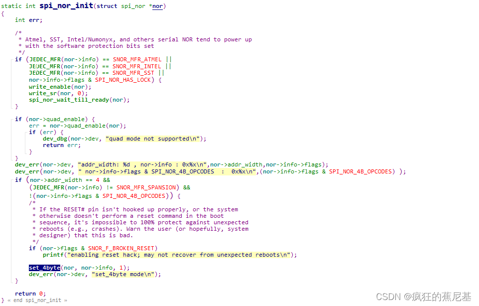
/* Send all the required SPI flash commands to initialize device */
nor->info = info;
ret = spi_nor_init(nor);
if (ret)
return ret;
nor->name = mtd->name;
nor->size = mtd->size;
nor->erase_size = mtd->erasesize;
nor->sector_size = mtd->erasesize;
#ifndef CONFIG_SPL_BUILD
printf("SF: Detected %s with page size ", nor->name);
print_size(nor->page_size, ", erase size ");
print_size(nor->erase_size, ", total ");
print_size(nor->size, "");
puts("\n");
#endif
return 0;
}
上面代码是在uboot 模式下,用户调用sf probe 命令触发的,其主要功能是设备handle的功能初始化赋值,设备检测,功能配置,设备初始化等。
- 设备的检测
设备检测通过info = spi_nor_read_id(nor);函数实现。代码会读取设备ID,然后与上述设备列表中的ID进行比较,判断 驱动是否支持。如果没有找到, 那么可以直接通过读到的ID 号判断设备是否存在, 是否需要menuconfi进行配置。如果读到的ID 都为0 ,那么一定是硬件设备的接线有问题,无法读到ID。
static const struct flash_info *spi_nor_read_id(struct spi_nor *nor)
{


	int			tmp;
	u8			id[SPI_NOR_MAX_ID_LEN];
	const struct flash_info	*info;

	tmp = nor->read_reg(nor, SPINOR_OP_RDID, id, SPI_NOR_MAX_ID_LEN);
	if (tmp < 0) {


		dev_dbg(nor->dev, "error %d reading JEDEC ID\n", tmp);
		return ERR_PTR(tmp);
	}

	info = spi_nor_ids;
	for (; info->name; info++) {


		if (info->id_len) {


			if (!memcmp(info->id, id, info->id_len))
				return info;
		}
	}

	dev_err(nor->dev, "unrecognized JEDEC id bytes: %02x, %02x, %02x\n",
		id[0], id[1], id[2]);
	return ERR_PTR(-ENODEV);
}
-
设备的4地址操作码的判断
下图代码是scan函数中的一部分,如果当前的设备容量大于16MB,那么必然需要使用4地址读写,4地址交互的方式有两种。一是:使用4地址操作码,进行操作。 如果芯片不支持4地址操作码, 那么会在初始化阶段使用4地址模式。
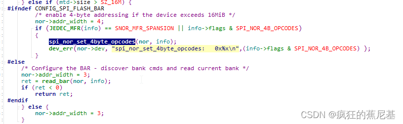
这里比较难理解, 从代码中,我们可以看到, 当设备的INFO 信息定义了 SPI_NOR_4B_OPCODES 属性, 那么一定会进入三地址转换为四地址的判断, 那么那么在读写操作的时候就会使用不同的操作码进行擦除读写。 如果不定义此属性, 不会对操作码进行转换,那么会在初始化阶段,开启4地址模式。 -
uboot sf 操作指令,用于测试4地址模式是否正常。
sf probe
sf erase 0x0 0x10000 /* erase one sector at 0x0 */
sf read 0x21000000  0x0 0x100
md.b 0x21000000
sf erase 0x1000000 0x1000 /* erase one sector at 16M */
sf read 0x22000000  0x0 0x100
md.b 0x22000000

sf write 0x10000000 0x1000000 0x100 /* write a page of data at 16M */
sf read 0x20000000  0x1000000 0x100 /* read back */
md.b 0x20000000

sf read 0x20000000  0x0 0x100
md.b 0x20000000