vtkCutter类
vtkCutter可以使用使用用户指定的隐式函数切割vtkDataSet。
vtkCutter是一个过滤器,可以使用vtkImplicitFunction 的任何子类来切割数据。也就是说,对应于隐式函数 F(x,y,z) = value(s) 创建了一个多边形表面,可以在其中指定一个或多个用于切割的值。
在VTK中,切割意味着将尺寸为N的单元减少为尺寸为N-1的切割表面。例如,一个四面体在被平面切割时(即vtkPlane隐函数)会生成三角形。(相比之下,裁剪采用 N 维单元并创建 N 维图元。)
vtkCutter通常用于“切片”数据集,生成可以可视化的表面。也可以使用vtkCutter来进行体绘制。vtkCutter通过生成多个从后到前排序(和渲染)的切割表面(通常是平面)来做到这一点。将表面设置为半透明以提供体积渲染效果。
注意,可以使用 1) 与数据集关联的标量值或 2) 与此类关联的隐式函数来切割数据。默认情况下,如果设置了隐式函数,则使用它来裁剪数据集,否则使用数据集标量来执行裁剪。
接口
轮廓上限个数
使用方法SetNumberOfContours设置轮廓的上限个数;方法GetNumberOfContours获取轮廓上限个数;
不过在设置SetValue时,如果超过了SetNumberOfContours所设置的上限个数时,上限值自动增加;
void SetNumberOfContours(int number) {

     this->ContourValues->SetNumberOfContours(number); }
vtkIdType GetNumberOfContours() {

     return this->ContourValues->GetNumberOfContours(); }
轮廓对应步进值
使用方法SetValue设置i轮廓对应的步进或者隐函数法线方向上的坐标。
void SetValue(int i, double value) {

     this->ContourValues->SetValue(i, value); }
double GetValue(int i) {

     return this->ContourValues->GetValue(i); }
double* GetValues() {

     return this->ContourValues->GetValues(); }
void GetValues(double* contourValues) {

     this->ContourValues->GetValues(contourValues); }
举例:
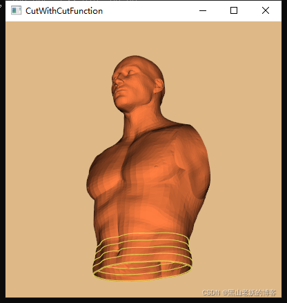
设置第一个轮廓的位置为0.99时:
cutter->SetValue(0, 0.99);
可见图像底部出现的一个轮廓;

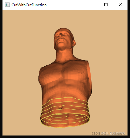
连续设置5个轮廓,间隔为20时;
cutter->SetNumberOfContours(5);
for (size_t i = 0; i < 5; i++) {


    cutter->SetValue(i, 0.99 + 20 * i);
}
可见图像底部出现的五个轮廓;
GenerateValues
使用方法GenerateValues可以设置轮廓上限个数和轮廓对应步进值,功能是在范围内生成几个轮廓,是从最小值min到最大值max这个范围内生成numContours个轮廓。
void GenerateValues(int numContours, double range[2]) {


     this->ContourValues->GenerateValues(numContours, range);
}
void GenerateValues(int numContours, double rangeStart, double rangeEnd) {


     this->ContourValues->GenerateValues(numContours, rangeStart, rangeEnd);
}
连续设置5个轮廓,间隔为20时;
cutter->GenerateValues(5, .99, .99 * 20 * 5);
效果同使用连续使用5次SetValue的效果是一样的。
设置隐函数
设置用于生成切割轮廓的隐函数,是继承于vtkImplicitFunction类的子类;常用于的是vtkPlane,用于平面切割;
virtual void SetCutFunction(vtkImplicitFunction*);
vtkGetObjectMacro(CutFunction, vtkImplicitFunction);
标识
如果启用此标志,则输出标量值将从隐式函数值插值,而不是从输入标量数据插值。
vtkSetMacro(GenerateCutScalars, vtkTypeBool);
vtkGetMacro(GenerateCutScalars, vtkTypeBool);
vtkBooleanMacro(GenerateCutScalars, vtkTypeBool);
如果启用此选项GenerateTriangles(默认开启),则输出将是三角形,否则,输出将是相交多边形警告:如果切割函数不是平面,则输出将是三维多边形,这可能很好看,但很难用下游进行计算。
vtkSetMacro(GenerateTriangles, vtkTypeBool);
vtkGetMacro(GenerateTriangles, vtkTypeBool);
vtkBooleanMacro(GenerateTriangles, vtkTypeBool);
输出精度
vtkSetClampMacro(OutputPointsPrecision, int, SINGLE_PRECISION, DEFAULT_PRECISION);
vtkGetMacro(OutputPointsPrecision, int);
注意
vtkCutter输出的vtkPolyData同普通的vtkPolyData一样,一条轮廓的结果和含有多条轮廓的结果是一样的,其内部的拓扑结果是散乱的。点与点的顺序也是散乱的,如果想单独获取一条轮廓线用,最好只生成一个轮廓线,这样结果方便处理;
官方例子
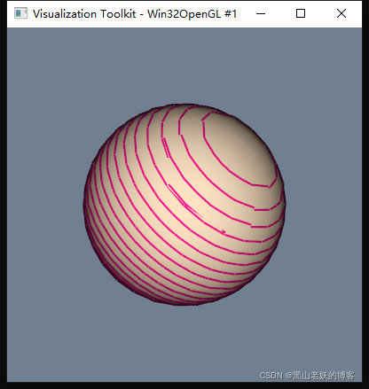
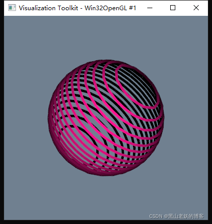
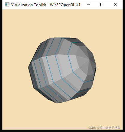
切割圆球的轮廓
vtkNew<vtkNamedColors> colors;

vtkSmartPointer<vtkPolyData> inputPolyData;
vtkNew<vtkSphereSource> sphereSource;
sphereSource->SetThetaResolution(30);
sphereSource->SetPhiResolution(15);
sphereSource->Update();
inputPolyData = sphereSource->GetOutput();

vtkNew<vtkPolyDataMapper> inputMapper;
inputMapper->SetInputData(inputPolyData);

// Create a plane to cut
vtkNew<vtkPlane> plane;
plane->SetOrigin(inputPolyData->GetCenter());
plane->SetNormal(1, 1, 1);

double minBound[3];
minBound[0] = inputPolyData->GetBounds()[0];
minBound[1] = inputPolyData->GetBounds()[2];
minBound[2] = inputPolyData->GetBounds()[4];

double maxBound[3];
maxBound[0] = inputPolyData->GetBounds()[1];
maxBound[1] = inputPolyData->GetBounds()[3];
maxBound[2] = inputPolyData->GetBounds()[5];

double center[3];
center[0] = inputPolyData->GetCenter()[0];
center[1] = inputPolyData->GetCenter()[1];
center[2] = inputPolyData->GetCenter()[2];

double distanceMin = sqrt(vtkMath::Distance2BetweenPoints(minBound, center));
double distanceMax = sqrt(vtkMath::Distance2BetweenPoints(maxBound, center));

// Create cutter
vtkNew<vtkCutter> cutter;
cutter->SetCutFunction(plane);
cutter->SetInputData(inputPolyData);
cutter->GenerateValues(20, -distanceMin, distanceMax);

vtkNew<vtkPolyDataMapper> cutterMapper;
cutterMapper->SetInputConnection(cutter->GetOutputPort());
cutterMapper->ScalarVisibilityOff();

// Create plane actor
vtkNew<vtkActor> planeActor;
planeActor->GetProperty()->SetColor(colors->GetColor3d("Deep_pink").GetData());
planeActor->GetProperty()->SetLineWidth(5);
planeActor->SetMapper(cutterMapper);

// Create input actor
vtkNew<vtkActor> inputActor;
inputActor->GetProperty()->SetColor(colors->GetColor3d("Bisque").GetData());
inputActor->SetMapper(inputMapper);

// Create renderers and add actors of plane and cube
vtkNew<vtkRenderer> renderer;
renderer->AddActor(planeActor); // display the rectangle resulting from the cut
renderer->AddActor(inputActor); // display the cube

// Add renderer to renderwindow and render
vtkNew<vtkRenderWindow> renderWindow;
renderWindow->AddRenderer(renderer);
renderWindow->SetWindowName("ContoursFromPolyData");
renderWindow->SetSize(600, 600);

vtkNew<vtkRenderWindowInteractor> interactor;
interactor->SetRenderWindow(renderWindow);
renderer->SetBackground(colors->GetColor3d("Slate_grey").GetData());
renderWindow->Render();
interactor->Initialize();
interactor->Start();
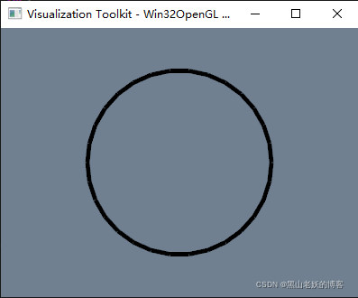
左图是同时显示轮廓和原始圆球;右图是单独显示vtkCutter生成的轮廓;
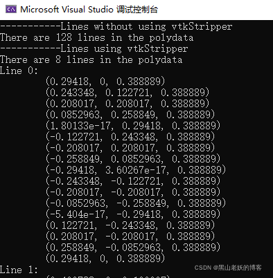
切割圆球的轮廓曲线点输出
vtkNew<vtkNamedColors> colors;
vtkColor3d lineColor = colors->GetColor3d("peacock");
vtkColor3d modelColor = colors->GetColor3d("silver");
vtkColor3d backgroundColor = colors->GetColor3d("wheat");

vtkNew<vtkSphereSource> modelSource;
vtkNew<vtkPlane> plane;
vtkNew<vtkCutter> cutter;
cutter->SetInputConnection(modelSource->GetOutputPort());
cutter->SetCutFunction(plane);
cutter->GenerateValues(10, -0.5, 0.5);

vtkNew<vtkPolyDataMapper> modelMapper;
modelMapper->SetInputConnection(modelSource->GetOutputPort());

vtkNew<vtkActor> model;
model->SetMapper(modelMapper);
model->GetProperty()->SetDiffuseColor(modelColor.GetData());
model->GetProperty()->SetInterpolationToFlat();

vtkNew<vtkStripper> stripper;
stripper->SetInputConnection(cutter->GetOutputPort());
stripper->JoinContiguousSegmentsOn();

vtkNew<vtkPolyDataMapper> linesMapper;
linesMapper->SetInputConnection(stripper->GetOutputPort());

vtkNew<vtkActor> lines;
lines->SetMapper(linesMapper);
lines->GetProperty()->SetDiffuseColor(lineColor.GetData());
lines->GetProperty()->SetLineWidth(3.0);

vtkNew<vtkRenderer> renderer;
vtkNew<vtkRenderWindow> renderWindow;

renderWindow->AddRenderer(renderer);
renderWindow->SetSize(640, 480);
renderWindow->SetWindowName("ExtractPolyLinesFromPolyData");

vtkNew<vtkRenderWindowInteractor> interactor;
interactor->SetRenderWindow(renderWindow);

// Add the actors to the renderer
renderer->AddActor(model);
renderer->AddActor(lines);
renderer->SetBackground(backgroundColor.GetData());
renderer->GetActiveCamera()->Azimuth(-45);
renderer->GetActiveCamera()->Elevation(-22.5);
renderer->ResetCamera();

// This starts the event loop and as a side effect causes an initial render.
renderWindow->Render();
interactor->Start();

// Extract the lines from the polydata
vtkIdType numberOfLines = cutter->GetOutput()->GetNumberOfLines();

std::cout << "-----------Lines without using vtkStripper" << std::endl;
std::cout << "There are " << numberOfLines << " lines in the polydata" << std::endl;

numberOfLines = stripper->GetOutput()->GetNumberOfLines();
vtkPoints* points = stripper->GetOutput()->GetPoints();
vtkCellArray* cells = stripper->GetOutput()->GetLines();

std::cout << "-----------Lines using vtkStripper" << std::endl;
std::cout << "There are " << numberOfLines << " lines in the polydata"<< std::endl;
// Older implementations of vtkCellArray use internal iterator APIs (not thread safe):
vtkIdType* indices;
vtkIdType numberOfPoints;
unsigned int lineCount = 0;
for (cells->InitTraversal(); cells->GetNextCell(numberOfPoints, indices); lineCount++)
{


    std::cout << "Line " << lineCount << ": " << std::endl;
    for (vtkIdType i = 0; i < numberOfPoints; i++)
    {


        double point[3];
        points->GetPoint(indices[i], point);
        std::cout << "\t(" << point[0] << ", " << point[1] << ", " << point[2] << ")" << std::endl;
    }
}
全半部分同第一个例子基本上是一致的,后部分是将vtkCutter的轮廓线输出点的坐标;
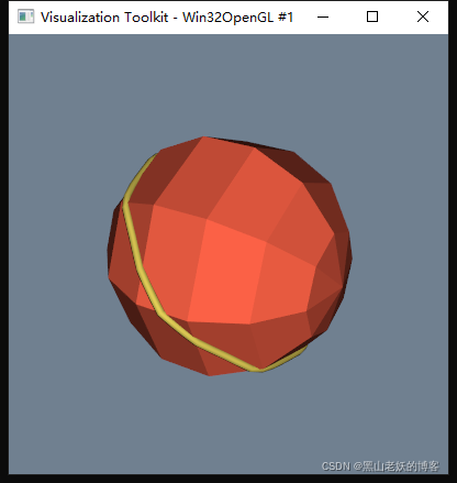
斜切割圆球的轮廓曲线形成管子显示
vtkSmartPointer<vtkPolyData> polyData;
vtkNew<vtkSphereSource> modelSource;
modelSource->Update();
polyData = modelSource->GetOutput();

double length = polyData->GetLength();

vtkNew<vtkPlane> plane;
plane->SetNormal(0, 1, 1);
plane->SetOrigin(polyData->GetCenter());

vtkNew<vtkCutter> cutter;
cutter->SetInputData(polyData);
cutter->SetCutFunction(plane);
cutter->GenerateValues(1, 0.0, 0.0);

vtkNew<vtkNamedColors> colors;

vtkNew<vtkPolyDataMapper> modelMapper;
modelMapper->SetInputData(polyData);

vtkNew<vtkActor> model;
model->SetMapper(modelMapper);
model->GetProperty()->SetColor(colors->GetColor3d("Tomato").GetData());
model->GetProperty()->SetInterpolationToFlat();

vtkNew<vtkStripper> stripper;
stripper->SetInputConnection(cutter->GetOutputPort());

vtkNew<vtkKochanekSpline> spline;
spline->SetDefaultTension(.5);

vtkNew<vtkSplineFilter> sf;
sf->SetInputConnection(stripper->GetOutputPort());
sf->SetSubdivideToSpecified();
sf->SetNumberOfSubdivisions(50);
sf->SetSpline(spline);
sf->GetSpline()->ClosedOn();

vtkNew<vtkTubeFilter> tubes;
tubes->SetInputConnection(sf->GetOutputPort());
tubes->SetNumberOfSides(8);
tubes->SetRadius(length / 100.0);

vtkNew<vtkPolyDataMapper> linesMapper;
linesMapper->SetInputConnection(tubes->GetOutputPort());
linesMapper->ScalarVisibilityOff();

vtkNew<vtkActor> lines;
lines->SetMapper(linesMapper);
lines->GetProperty()->SetColor(colors->GetColor3d("Banana").GetData());

vtkNew<vtkRenderer> renderer;
renderer->UseHiddenLineRemovalOn();

vtkNew<vtkRenderWindow> renderWindow;
vtkNew<vtkRenderWindowInteractor> interactor;
interactor->SetRenderWindow(renderWindow);

// Add the actors to the renderer
renderer->AddActor(model);
renderer->AddActor(lines);

renderer->ResetCamera();
renderer->SetBackground(colors->GetColor3d("SlateGray").GetData());
renderer->GetActiveCamera()->Azimuth(300);
renderer->GetActiveCamera()->Elevation(30);
renderWindow->AddRenderer(renderer);
renderWindow->SetSize(400, 400);
renderWindow->SetWindowName("FitSplineToCutterOutput");

// This starts the event loop and as a side effect causes an initial
// render.
renderWindow->Render();
interactor->Start();

// Extract the lines from the polydata
vtkIdType numberOfLines = cutter->GetOutput()->GetNumberOfLines();

std::cout << "-----------Lines without using vtkStripper" << std::endl;
if (numberOfLines == 1) {


    std::cout << "There is " << numberOfLines << " line in the polydata" << std::endl;
}
else {


    std::cout << "There are " << numberOfLines << " lines in the polydata" << std::endl;
}
numberOfLines = stripper->GetOutput()->GetNumberOfLines();
vtkPoints* points = stripper->GetOutput()->GetPoints();
vtkCellArray* cells = stripper->GetOutput()->GetLines();

std::cout << "-----------Lines using vtkStripper" << std::endl;
if (numberOfLines == 1) {


    std::cout << "There is " << numberOfLines << " line in the polydata" << std::endl;
}
else {


    std::cout << "There are " << numberOfLines << " lines in the polydata" << std::endl;
}

// Older implementations of vtkCellArray use internal iterator APIs (not
// thread safe):
vtkIdType* indices;
vtkIdType numberOfPoints;
unsigned int lineCount = 0;
for (cells->InitTraversal(); cells->GetNextCell(numberOfPoints, indices); lineCount++) {


    std::cout << "Line " << lineCount << ": " << std::endl;
    for (vtkIdType i = 0; i < numberOfPoints; i++) {


        double point[3];
        points->GetPoint(indices[i], point);
        std::cout << "\t(" << point[0] << ", " << point[1] << ", " << point[2] << ")" << std::endl;
    }
}
使用一个斜平面对圆球进行Cut,获取轮廓后,插值,并使用vtkTubeFilter形成细管子展示;
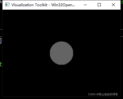
切割圆球轮廓转vtkImageData数据
将切割后的轮廓,转换为二维灰度图像;
vtkNew<vtkSphereSource> sphereSource;
sphereSource->SetPhiResolution(30);
sphereSource->SetThetaResolution(30);
sphereSource->SetCenter(40, 40, 0);
sphereSource->SetRadius(20);

// generate circle by cutting the sphere with an implicit plane
// (through its center, axis-aligned)
vtkNew<vtkCutter> circleCutter;
circleCutter->SetInputConnection(sphereSource->GetOutputPort());
vtkNew<vtkPlane> cutPlane;
cutPlane->SetOrigin(sphereSource->GetCenter());
cutPlane->SetNormal(0, 0, 1);
circleCutter->SetCutFunction(cutPlane);

vtkNew<vtkStripper> stripper;
stripper->SetInputConnection(circleCutter->GetOutputPort()); // valid circle
stripper->Update();
renderPolygon(stripper->GetOutput());
// that's our circle
auto circle = stripper->GetOutput();
// prepare the binary image's voxel grid
vtkNew<vtkImageData> whiteImage;
double bounds[6];
circle->GetBounds(bounds);
double spacing[3]; // desired volume spacing
spacing[0] = 0.5;
spacing[1] = 0.5;
spacing[2] = 0.5;
whiteImage->SetSpacing(spacing);

// compute dimensions
int dim[3];
for (int i = 0; i < 3; i++) {


    dim[i] = static_cast<int>(ceil((bounds[i * 2 + 1] - bounds[i * 2]) / spacing[i])) + 1;
    if (dim[i] < 1)
        dim[i] = 1;
}
whiteImage->SetDimensions(dim);
whiteImage->SetExtent(0, dim[0] - 1, 0, dim[1] - 1, 0, dim[2] - 1);
double origin[3];

// NOTE: I am not sure whether or not we had to add some offset!
origin[0] = bounds[0]; // + spacing[0] / 2;
origin[1] = bounds[2]; // + spacing[1] / 2;
origin[2] = bounds[4]; // + spacing[2] / 2;
whiteImage->SetOrigin(origin);
whiteImage->AllocateScalars(VTK_UNSIGNED_CHAR, 1);

// fill the image with foreground voxels:
unsigned char inval = 100;
unsigned char outval = 0;
vtkIdType count = whiteImage->GetNumberOfPoints();
for (vtkIdType i = 0; i < count; ++i) {


    whiteImage->GetPointData()->GetScalars()->SetTuple1(i, inval);
}

// sweep polygonal data (this is the important thing with contours!)
vtkNew<vtkLinearExtrusionFilter> extruder;
extruder->SetInputData(circle);
extruder->SetScaleFactor(1.);
extruder->SetExtrusionTypeToVectorExtrusion();
extruder->SetVector(0, 0, 1);
extruder->Update();

// polygonal data --> image stencil:
vtkNew<vtkPolyDataToImageStencil> pol2stenc;
pol2stenc->SetTolerance(1); // important if extruder->SetVector(0, 0, 1) !!!
pol2stenc->SetInputConnection(extruder->GetOutputPort());
pol2stenc->SetOutputOrigin(origin);
pol2stenc->SetOutputSpacing(spacing);
pol2stenc->SetOutputWholeExtent(whiteImage->GetExtent());
pol2stenc->Update();

// cut the corresponding white image and set the background:
vtkNew<vtkImageStencil> imgstenc;
imgstenc->SetInputData(whiteImage);
imgstenc->SetStencilConnection(pol2stenc->GetOutputPort());
imgstenc->ReverseStencilOff();
imgstenc->SetBackgroundValue(outval);
imgstenc->Update();
imgstenc->GetOutput()->Print(std::cout);
vtkSmartPointer<vtkImageData> img = imgstenc->GetOutput();

vtkNew<vtkImageViewer2> imageViewer;
imageViewer->SetInputData(img);
vtkNew<vtkRenderWindowInteractor> renderWindowInteractor;
imageViewer->SetupInteractor(renderWindowInteractor);
imageViewer->Render();

renderWindowInteractor->Start();
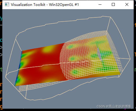
流体切面
vtkNew<vtkNamedColors> colors;
vtkNew<vtkRenderer> ren1;

vtkNew<vtkRenderWindow> renWin;
renWin->AddRenderer(ren1);

vtkNew<vtkRenderWindowInteractor> iren;
iren->SetRenderWindow(renWin);

// cut data
vtkNew<vtkMultiBlockPLOT3DReader> pl3d;
pl3d->SetXYZFileName("D:\\combxyz.bin");
pl3d->SetQFileName("D:\\combq.bin");
pl3d->SetScalarFunctionNumber(100);
pl3d->SetVectorFunctionNumber(202);
pl3d->Update();

vtkStructuredGrid* sg = dynamic_cast<vtkStructuredGrid*>(pl3d->GetOutput()->GetBlock(0));

vtkNew<vtkPlane> plane;
plane->SetOrigin(sg->GetCenter());
plane->SetNormal(-0.287, 0, 0.9579);

vtkNew<vtkCutter> planeCut;
planeCut->SetInputData(pl3d->GetOutput()->GetBlock(0));
planeCut->SetCutFunction(plane);

vtkNew<vtkDataSetMapper> cutMapper;
cutMapper->SetInputConnection(planeCut->GetOutputPort());
cutMapper->SetScalarRange(sg->GetPointData()->GetScalars()->GetRange());

vtkNew<vtkActor> cutActor;
cutActor->SetMapper(cutMapper);

// extract plane
vtkNew<vtkStructuredGridGeometryFilter> compPlane;
compPlane->SetInputData(sg);
compPlane->SetExtent(0, 100, 0, 100, 9, 9);

vtkNew<vtkPolyDataMapper> planeMapper;
planeMapper->SetInputConnection(compPlane->GetOutputPort());
planeMapper->ScalarVisibilityOff();

vtkNew<vtkActor> planeActor;
planeActor->SetMapper(planeMapper);
planeActor->GetProperty()->SetRepresentationToWireframe();
planeActor->GetProperty()->SetColor(colors->GetColor3d("Wheat").GetData());

// outline
vtkNew<vtkStructuredGridOutlineFilter> outline;
outline->SetInputData(pl3d->GetOutput()->GetBlock(0));

vtkNew<vtkPolyDataMapper> outlineMapper;
outlineMapper->SetInputConnection(outline->GetOutputPort());

vtkNew<vtkActor> outlineActor;
outlineActor->SetMapper(outlineMapper);
outlineActor->GetProperty()->SetColor(colors->GetColor3d("Wheat").GetData());

// Add the actors to the renderer, set the background and size
ren1->AddActor(outlineActor);
ren1->AddActor(planeActor);
ren1->AddActor(cutActor);
ren1->SetBackground(colors->GetColor3d("SlateGray").GetData());

renWin->SetSize(640, 480);
renWin->SetWindowName("CutStructuredGrid");

auto camera = ren1->GetActiveCamera();
camera->SetPosition(5.02611, -23.535, 50.3979);
camera->SetFocalPoint(9.33614, 0.0414149, 30.112);
camera->SetViewUp(-0.0676794, 0.657814, 0.750134);
camera->SetDistance(31.3997);
camera->SetClippingRange(12.1468, 55.8147);

// render the image
renWin->Render();
iren->Start();
使用平面切割立方体
vtkNew<vtkNamedColors> colors;
vtkNew<vtkCubeSource> cube;
cube->SetXLength(40);
cube->SetYLength(30);
cube->SetZLength(20);
vtkNew<vtkPolyDataMapper> cubeMapper;
cubeMapper->SetInputConnection(cube->GetOutputPort());

// Create a plane to cut,here it cuts in the XZ direction (xz
// normal=(1,0,0);XY =(0,0,1),YZ =(0,1,0)
vtkNew<vtkPlane> plane;
plane->SetOrigin(10, 0, 0);
plane->SetNormal(1, 0, 0);

// Create cutter
vtkNew<vtkCutter> cutter;
cutter->SetCutFunction(plane);
cutter->SetInputConnection(cube->GetOutputPort());
cutter->Update();

vtkNew<vtkPolyDataMapper> cutterMapper;
cutterMapper->SetInputConnection(cutter->GetOutputPort());
cutterMapper->SetResolveCoincidentTopologyToPolygonOffset();

// Create plane actor
vtkNew<vtkActor> planeActor;
planeActor->GetProperty()->SetColor(colors->GetColor3d("Yellow").GetData());
planeActor->GetProperty()->SetLineWidth(2);
planeActor->GetProperty()->SetAmbient(1.0);
planeActor->GetProperty()->SetDiffuse(0.0);
planeActor->SetMapper(cutterMapper);

// Create cube actor
vtkNew<vtkActor> cubeActor;
cubeActor->GetProperty()->SetColor(colors->GetColor3d("Aquamarine").GetData());
cubeActor->GetProperty()->SetOpacity(0.5);
cubeActor->SetMapper(cubeMapper);

// Create renderers and add actors of plane and cube
vtkNew<vtkRenderer> renderer;
renderer->AddActor(planeActor); // display the rectangle resulting from the cut
renderer->AddActor(cubeActor);  // display the cube

// Add renderer to renderwindow and render
vtkNew<vtkRenderWindow> renderWindow;
renderWindow->AddRenderer(renderer);
renderWindow->SetSize(400, 400);
renderWindow->SetWindowName("Cutter");

vtkNew<vtkRenderWindowInteractor> interactor;
interactor->SetRenderWindow(renderWindow);
renderer->SetBackground(colors->GetColor3d("Silver").GetData());
renderWindow->Render();

auto camera = renderer->GetActiveCamera();
camera->SetPosition(-37.2611, -86.2155, 44.841);
camera->SetFocalPoint(0.569422, -1.65124, -2.49482);
camera->SetViewUp(0.160129, 0.42663, 0.890138);
camera->SetDistance(104.033);
camera->SetClippingRange(55.2019, 165.753);

renderWindow->Render();
interactor->Start();

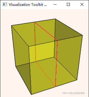
使用平面切割六面体
vtkNew<vtkNamedColors> colors;

// Setup the coordinates of eight points
// (the two faces must be in counter clockwise order as viewed from the
// outside)
std::array<std::array<double, 3>, 8> pointCoords{

     {

    {

    {

    0.0, 0.0, 0.0}},
                                                  {

    {

    1.0, 0.0, 0.0}},
                                                  {

    {

    1.0, 1.0, 0.0}},
                                                  {

    {

    0.0, 1.0, 0.0}},
                                                  {

    {

    0.0, 0.0, 1.0}},
                                                  {

    {

    1.0, 0.0, 1.0}},
                                                  {

    {

    1.0, 1.0, 1.0}},
                                                  {

    {

    0.0, 1.0, 1.0}}} };

// Create the points and a hexahedron from the points.
vtkNew<vtkPoints> points;
vtkNew<vtkHexahedron> hexa;
for (auto i = 0; i < pointCoords.size(); ++i) {


    points->InsertNextPoint(pointCoords[i].data());
    hexa->GetPointIds()->SetId(i, i);
}

// Add the hexahedron to a cell array.
vtkNew<vtkCellArray> hexs;
hexs->InsertNextCell(hexa);

// Add the points and hexahedron to an unstructured grid.
vtkNew<vtkUnstructuredGrid> uGrid;
uGrid->SetPoints(points);
uGrid->InsertNextCell(hexa->GetCellType(), hexa->GetPointIds());

// Extract the outer (polygonal) surface.
vtkNew<vtkDataSetSurfaceFilter> surface;
surface->SetInputData(uGrid);
surface->Update();

vtkNew<vtkDataSetMapper> aBeamMapper;
aBeamMapper->SetInputConnection(surface->GetOutputPort());
vtkNew<vtkActor> aBeamActor;
aBeamActor->SetMapper(aBeamMapper);
aBeamActor->AddPosition(0, 0, 0);
aBeamActor->GetProperty()->SetColor(colors->GetColor3d("Yellow").GetData());
aBeamActor->GetProperty()->SetOpacity(0.60);
aBeamActor->GetProperty()->EdgeVisibilityOn();
aBeamActor->GetProperty()->SetEdgeColor(colors->GetColor3d("Black").GetData());
aBeamActor->GetProperty()->SetLineWidth(1.5);

// Create a plane to cut, here it cuts in the XZ direction
// (xz normal=(1,0,0); XY =(0,0,1), YZ =(0,1,0)
vtkNew<vtkPlane> plane;
plane->SetOrigin(0.5, 0, 0);
plane->SetNormal(1, 0, 0);

// Create cutter
vtkNew<vtkCutter> cutter;
cutter->SetCutFunction(plane);
cutter->SetInputData(aBeamActor->GetMapper()->GetInput());
cutter->Update();
vtkNew<vtkPolyDataMapper> cutterMapper;
cutterMapper->SetInputConnection(cutter->GetOutputPort());

// Create plane actor
vtkNew<vtkActor> planeActor;
planeActor->GetProperty()->SetColor(colors->GetColor3d("Red").GetData());
planeActor->GetProperty()->SetLineWidth(2);
planeActor->SetMapper(cutterMapper);

// Create a renderer, render window, and interactor
vtkNew<vtkRenderer> renderer;
vtkNew<vtkRenderWindow> renderWindow;
renderWindow->SetWindowName("DatasetSurface");
renderWindow->AddRenderer(renderer);
vtkNew<vtkRenderWindowInteractor> renderWindowInteractor;
renderWindowInteractor->SetRenderWindow(renderWindow);

// Add the actors to the scene
renderer->AddActor(aBeamActor);
renderer->AddActor(planeActor);
renderer->SetBackground(colors->GetColor3d("Seashell").GetData());

renderer->ResetCamera();
renderer->GetActiveCamera()->Azimuth(-25);
renderer->GetActiveCamera()->Elevation(30);

// Render and interact
renderWindow->Render();
renderWindowInteractor->Start();
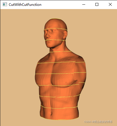
使用平面分割人像多边形数据
std::string inputFilename = "D:\\Torso.vtp";

int numberOfCuts = 10;
vtkNew<vtkNamedColors> colors;

vtkNew<vtkXMLPolyDataReader> reader;
reader->SetFileName(inputFilename.c_str());
reader->Update();

double bounds[6];
reader->GetOutput()->GetBounds(bounds);
std::cout << "Bounds: " << bounds[0] << ", " << bounds[1] << " " << bounds[2]
<< ", " << bounds[3] << " " << bounds[4] << ", " << bounds[5]
<< std::endl;

vtkNew<vtkPlane> plane;
plane->SetOrigin((bounds[1] + bounds[0]) / 2.0, (bounds[3] + bounds[2]) / 2.0,
    bounds[4]);
plane->SetNormal(0, 0, 1);

// Create cutter
double high = plane->EvaluateFunction((bounds[1] + bounds[0]) / 2.0, (bounds[3] + bounds[2]) / 2.0, bounds[5]);

vtkNew<vtkCutter> cutter;
cutter->SetInputConnection(reader->GetOutputPort());
cutter->SetCutFunction(plane);
cutter->GenerateValues(numberOfCuts, .99, .99 * high);

vtkNew<vtkPolyDataMapper> cutterMapper;
cutterMapper->SetInputConnection(cutter->GetOutputPort());
cutterMapper->ScalarVisibilityOff();

// Create cut actor
vtkNew<vtkActor> cutterActor;
cutterActor->GetProperty()->SetColor(colors->GetColor3d("Banana").GetData());
cutterActor->GetProperty()->SetLineWidth(2);
cutterActor->SetMapper(cutterMapper);

// Create model actor
vtkNew<vtkPolyDataMapper> modelMapper;
modelMapper->SetInputConnection(reader->GetOutputPort());
modelMapper->ScalarVisibilityOff();

vtkNew<vtkActor> modelActor;
modelActor->GetProperty()->SetColor(colors->GetColor3d("Flesh").GetData());
modelActor->SetMapper(modelMapper);

// Create renderers and add actors of plane and model
vtkNew<vtkRenderer> renderer;
renderer->AddActor(cutterActor);
renderer->AddActor(modelActor);

// Add renderer to renderwindow and render
vtkNew<vtkRenderWindow> renderWindow;
renderWindow->AddRenderer(renderer);
renderWindow->SetSize(400, 400);

vtkNew<vtkRenderWindowInteractor> interactor;
interactor->SetRenderWindow(renderWindow);

renderer->SetBackground(colors->GetColor3d("Burlywood").GetData());
renderer->GetActiveCamera()->SetPosition(0, -1, 0);
renderer->GetActiveCamera()->SetFocalPoint(0, 0, 0);
renderer->GetActiveCamera()->SetViewUp(0, 0, 1);
renderer->GetActiveCamera()->Azimuth(30);
renderer->GetActiveCamera()->Elevation(30);

renderer->ResetCamera();
renderWindow->Render();
renderWindow->SetWindowName("CutWithCutFunction");

interactor->Start();