设备树
设备树(Device tree)是一套用来描述硬件属相的规则。ARM Linux采用设备树机制源于2011年3月份Linux创始人Linus Torvalds发的一封邮件,在这封邮件中他提倡ARM平台应该参考其他平台如PowerPC的设备树机制描述硬件。
DTS(Device tree syntax,另一种说法是Device tree source)是设备树源文件,为了方便阅读及修改,采用文本格式。DTC(Device tree compiler)是一个小工具,负责将DTS转换成DTB(Device tree blob)。DTB是DTS的二进制形式,供机器使用。使用中,我们首先根据硬件修改DTS文件,然后在编译的时候通过DTC工具将DTS文件转换成DTB文件,然后将DTB文件烧写到机器上(如emmc,磁盘等存储介质)。
系统启动时,fastboot(或者类似的启动程序,如Uboot)在启动内核前将DTB文件读到内存中,跳转到内核执行的同时将DTB起始地址传给内核。内核通过起始地址就可以根据DTB的结构解析整个设备树。
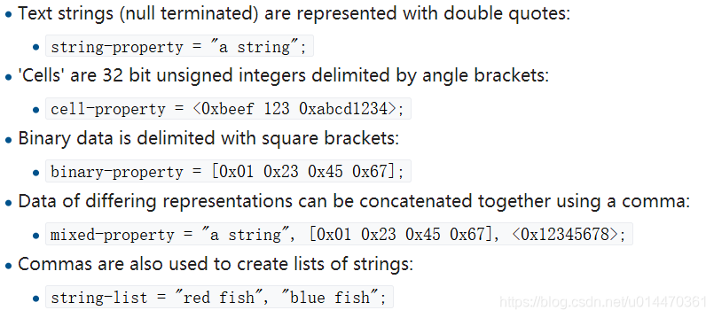
基本的数据格式
/ {
    node1 {
        a-string-property = "A string";
        a-string-list-property = "first string", "second string";
        // hex is implied in byte arrays. no '0x' prefix is required
        a-byte-data-property = [01 23 34 56];
        child-node1 {
            first-child-property;
            second-child-property = <1>;
            a-string-property = "Hello, world";
        };
        child-node2 {
        };
    };
    node2 {
        an-empty-property;
        a-cell-property = <1 2 3 4>; /* each number (cell) is a uint32 */
        child-node1 {
        };
    };
};
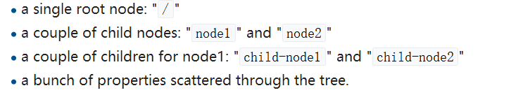
设备数示例图解
(1)初始结构
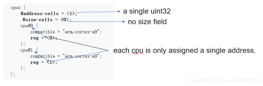
(2)CPUS

(3)地址
A: CPU addressing
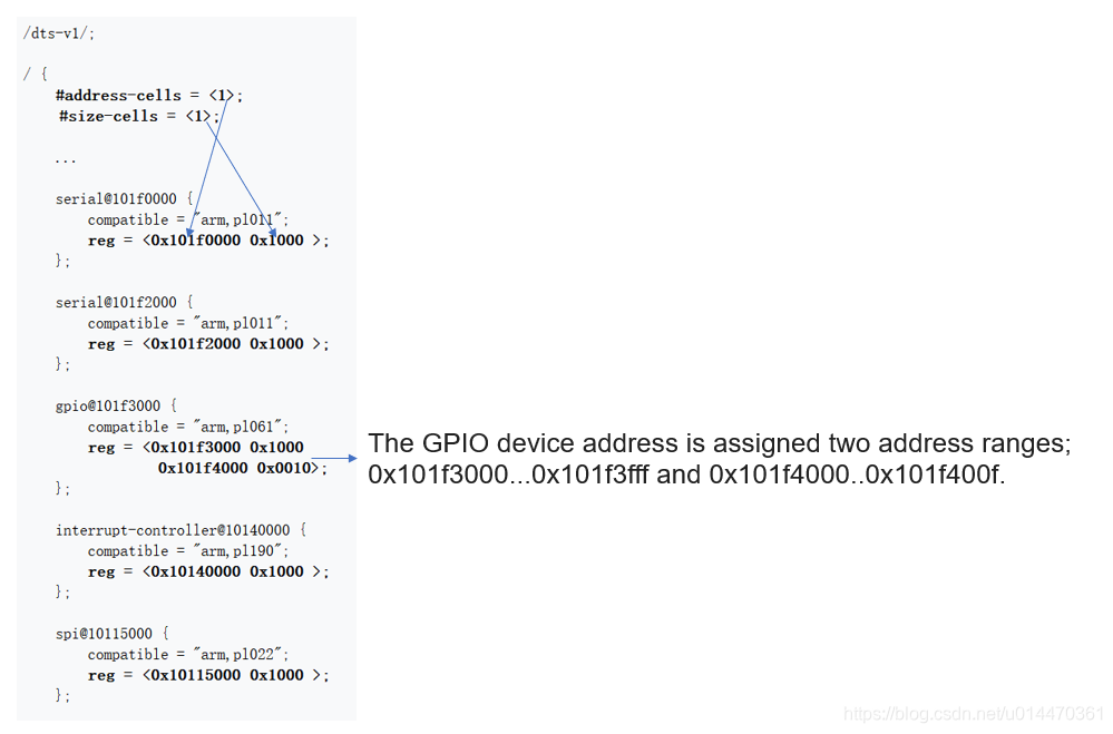
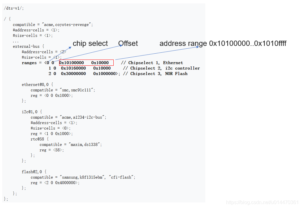
B:Memory Mapped Devices
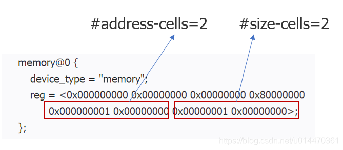
注意:64 bit machines may use a value of 2 for #address-cells and #size-cells to get 64 bit addressing in the device tree. 如下:
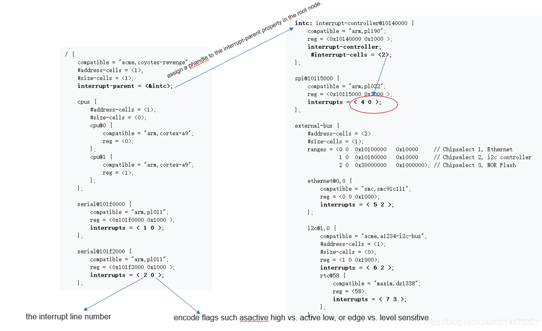
C:Interrupts
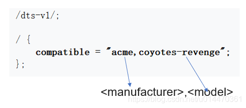
/dts-v1/;
/ {
compatible = "acme,coyotes-revenge";
#address-cells = <1>;
#size-cells = <1>;
interrupt-parent = <&intc>;
cpus {
#address-cells = <1>;
#size-cells = <0>;
cpu@0 {
compatible = "arm,cortex-a9";
reg = <0>;
};
cpu@1 {
compatible = "arm,cortex-a9";
reg = <1>;
};
};
serial@101f0000 {
compatible = "arm,pl011";
reg = <0x101f0000 0x1000 >;
interrupts = < 1 0 >;
};
serial@101f2000 {
compatible = "arm,pl011";
reg = <0x101f2000 0x1000 >;
interrupts = < 2 0 >;
};
gpio@101f3000 {
compatible = "arm,pl061";
reg = <0x101f3000 0x1000
0x101f4000 0x0010>;
interrupts = < 3 0 >;
};
intc: interrupt-controller@10140000 {
compatible = "arm,pl190";
reg = <0x10140000 0x1000 >;
interrupt-controller;
#interrupt-cells = <2>;
};
spi@10115000 {
compatible = "arm,pl022";
reg = <0x10115000 0x1000 >;
interrupts = < 4 0 >;
};
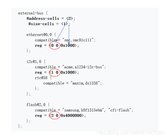
external-bus {
#address-cells = <2>
#size-cells = <1>;
ranges = <0 0 0x10100000 0x10000 // Chipselect 1, Ethernet
1 0 0x10160000 0x10000 // Chipselect 2, i2c controller
2 0 0x30000000 0x1000000>; // Chipselect 3, NOR Flash
ethernet@0,0 {
compatible = "smc,smc91c111";
reg = <0 0 0x1000>;
interrupts = < 5 2 >;
};
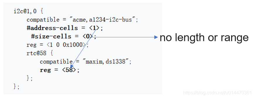
i2c@1,0 {
compatible = "acme,a1234-i2c-bus";
#address-cells = <1>;
#size-cells = <0>;
reg = <1 0 0x1000>;
interrupts = < 6 2 >;
rtc@58 {
compatible = "maxim,ds1338";
reg = <58>;
interrupts = < 7 3 >;
};
};
flash@2,0 {
compatible = "samsung,k8f1315ebm", "cfi-flash";
reg = <2 0 0x4000000>;
};
};
};
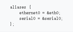
D:aliases Node(别名节点)
E:chosen Node
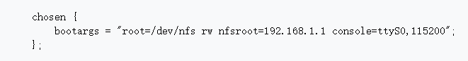
The chosen node doesn’t represent a real device, but serves as a place for passing data between firmware and the operating system, like boot arguments.