版权声明:本文为博主原创文章,遵循 CC 4.0 BY-SA 版权协议,转载请附上原文出处链接和本声明。
这篇跟第一篇一个样,我这里只是方便做下记录而已,各位看官随意选择阅读。需创建两个文件my_i2c.h与my_i2c.c,该代码是参照正点原子实例代码修改。(EFM32与MPU9250模拟I2C通讯)
my_i2c.h:
#ifndef __MY_I2C_H
#define	__MY_I2C_H

#include <stdint.h>
#include "em_chip.h"
#include "em_cmu.h"
#include "em_gpio.h"


/* Using PA0 (SDA) and PA1 (SCL) */

#define SDA_IN()   GPIO_PinModeSet(gpioPortA, 0, gpioModeInput, 1);          //PA0 输入模式
#define SDA_OUT()  GPIO_PinModeSet(gpioPortA, 0, gpioModePushPull, 1);       //PA0 输出模式

//IO操作函数
//SCL   PA1
#define I2C_SCL_1()  	 {GPIO_PinOutSet(gpioPortA,1);}						 //高
#define I2C_SCL_0()  	 {GPIO_PinOutClear(gpioPortA,1);} 					 //低
//SDA   PA0
#define I2C_SDA_1()  	 {GPIO_PinOutSet(gpioPortA,0);}						 //高
#define I2C_SDA_0()  	 {GPIO_PinOutClear(gpioPortA,0);} 					 //低

#define I2C_SDA_READ()   (GPIO_PinInGet(gpioPortA, 0))   					 //输入SDA


//IIC所有操作函数
void IIC_Init(void);                //初始化IIC的IO口
void IIC_Start(void);				//发送IIC开始信号
void IIC_Stop(void);	  			//发送IIC停止信号
void IIC_Send_Byte(uint8_t txd);			//IIC发送一个字节
uint8_t IIC_Read_Byte(unsigned char ack);//IIC读取一个字节
uint8_t IIC_Wait_Ack(void); 				//IIC等待ACK信号
void IIC_Ack(void);					//IIC发送ACK信号
void IIC_NAck(void);				//IIC不发送ACK信号

void IIC_Write_One_Byte(uint8_t daddr,uint8_t addr,uint8_t data);
uint8_t IIC_Read_One_Byte(uint8_t daddr,uint8_t addr);

#endif
my_i2c.c:
#include "em_i2c.h"
#include "em_emu.h"
#include "my_i2c.h"
#include "em_cmu.h"
#include "em_gpio.h"

/**
 * 长延时函数	 us=1,延时1us
 *
 * @author jun (2019/5/11)
 *
 * @param us
 *
 * @return void
 */
static void delay_us(uint32_t us)
{
  uint32_t i;
  for(; us!=0; us--)
       for (i=0; i<10; i++);        //如果I2C时钟线交叉时,增大i的值即可
}

/**
 * IIC初始化函数
 *
 * @author jun (2019/5/11)
 *
 * @param void
 *
 * @return void
 */
void IIC_Init(void)
{
	CMU_ClockEnable(cmuClock_GPIO, true);

	/* Starting LFXO and waiting until it is stable */
	CMU_OscillatorEnable(cmuOsc_LFRCO, true, true);
	/* Routing the LFXO clock to the RTC */
	CMU_ClockSelectSet(cmuClock_LFA, cmuSelect_LFRCO);		//32KHz
	/* Configure interrupt pin*/
	GPIO_PinModeSet(gpioPortC, 4, gpioModeInput, 0);
	/* Using PA0 (SDA) and PA1 (SCL) */
	GPIO_PinModeSet(gpioPortA, 0, gpioModeWiredAndPullUpFilter, 1);		//SDA	PA0
	GPIO_PinModeSet(gpioPortA, 1, gpioModeWiredAndPullUpFilter, 1);		//SCL	PA1

	I2C_SDA_1();
	I2C_SCL_1();
}

/**
 * IIC起始信号
 *
 * @author jun (2019/5/11)
 *
 * @param void
 *
 * @return void
 */
void IIC_Start(void)
{
	//SDA_OUT();     //sda线输出
	I2C_SDA_1();
	I2C_SCL_1();
	delay_us(4);
 	I2C_SDA_0();//START:when CLK is high,DATA change form high to low
	delay_us(4);
	I2C_SCL_0();//钳住I2C总线,准备发送或接收数据
}

/**
 * IIC停止信号
 *
 * @author jun (2019/5/11)
 *
 * @param void
 *
 * @return void
 */
void IIC_Stop(void)
{
	//SDA_OUT();//sda线输出
	I2C_SCL_0();
	I2C_SDA_0();//STOP:when CLK is high DATA change form low to high
 	delay_us(4);
	I2C_SCL_1();
	delay_us(4);
	I2C_SDA_1();//发送I2C总线结束信号
}


/**
 * 等待应答信号到来
 *
 * @author jun (2019/5/11)
 *
 * @param void
 *
 * @return 1,接收应答失败
 *         0,接收应答成功
 */
uint8_t IIC_Wait_Ack(void)
{
	uint8_t ucErrTime=0;
	//SDA_IN();      //SDA设置为输入
	I2C_SDA_1(); delay_us(1);
	I2C_SCL_1(); delay_us(1);
	while(I2C_SDA_READ())
	{
		ucErrTime++;
		if(ucErrTime>250)
		{
			IIC_Stop();
			return 1;
		}
	}
	I2C_SCL_0();//时钟输出0
	return 0;
}

/**
 * 产生ACK应答
 *
 * @author jun (2019/5/11)
 *
 * @param void
 *
 * @return void
 */
void IIC_Ack(void)
{
	I2C_SCL_0();
	//SDA_OUT();
	I2C_SDA_0();
	delay_us(2);
	I2C_SCL_1();
	delay_us(2);
	I2C_SCL_0();
}

/**
 * 不产生ACK应答
 *
 * @author jun (2019/5/11)
 *
 * @param void
 *
 * @return void
 */
void IIC_NAck(void)
{
	I2C_SCL_0();
	//SDA_OUT();
	I2C_SDA_1();
	delay_us(2);
	I2C_SCL_1();
	delay_us(2);
	I2C_SCL_0();
}

/**
 * IIC发送一个字节
 *
 * @author jun (2019/5/11)
 *
 * @param txd
 *
 * 返回从机有无应答
 * @return  1,有应答
 *          0,无应答
 */
void IIC_Send_Byte(uint8_t txd)
{
    uint8_t t;
	//SDA_OUT();
    I2C_SCL_0();//拉低时钟开始数据传输
    for(t=0;t<8;t++)
    {
		if(txd&0x80) {
			I2C_SDA_1();
		} else {
			I2C_SDA_0();
		}
		delay_us(2);   	 //对TEA5767这三个延时都是必须的
		I2C_SCL_1();
		delay_us(2);
		I2C_SCL_0();
		if(t == 7) {
			I2C_SDA_1(); // 释放总线
		}
		txd<<=1;         /* 左移一个bit */
		delay_us(2);
    }
}

/**
 * 读1个字节
 *
 * @author jun (2019/5/11)
 *
 * @param ack
 * 			    ack=1时,发送ACK
 * 				ack=0时,发送nACK
 *
 * @return
 *
 */
uint8_t IIC_Read_Byte(uint8_t ack)
{
	uint8_t i,receive=0;
    //SDA_IN();//SDA设置为输入
    for(i=0;i<8;i++)
	{
        I2C_SCL_0();
        delay_us(2);
		I2C_SCL_1();
        receive<<=1;
        if(I2C_SDA_READ())receive++;
		delay_us(1);
    }
    if (!ack)
        IIC_NAck();//发送nACK
    else
        IIC_Ack(); //发送ACK
    return receive;
}
调用
#include "em_cmu.h"
#include "em_gpio.h"
#include "my_i2c.h"
#include "mpu9250.h"


static void Delayms(uint32_t ms)
{
  uint32_t i;

  for(; ms != 0; ms--)
       for (i=0; i<500; i++);
}


int main(void)
{
    uint8_t res = 0;
    IIC_Init();
    Init_MPU9250();
    res=MPU_Read_Byte(MPU9250_ADDR,MPU_DEVICE_ID_REG);
    Delayms(100);
    MPU_Write_Byte(MPU9250_ADDR,MPU_INTBP_CFG_REG,0X82);
    Delayms(1);
	res=MPU_Read_Byte(MPU9250_ADDR,MPU_INTBP_CFG_REG);
    printf("res : %d \r\n", res);
}
往MPU9250中的0x37寄存器,写入0x82的数据,波形如下:

读取MPU9250中的0x37寄存器的数据(0x82),波形如下:

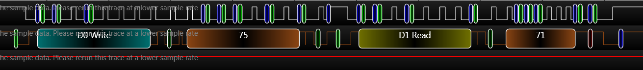
读取MPU9250中的0x75寄存器的数据(0x71),也就是ChipID值,波形如下:
//时间太短,延时不够长
 static void delay_us(uint32_t us)
{
  uint32_t i;
  for(; us!=0; us--)
       for (i=0; i<1; i++);
}
//如果I2C时钟线的停止位与起始位交叉时,修改my_i2c.c中的delay_us()函数中的 i 值,增大即可。

//时间修改长点
 static void delay_us(uint32_t us)
{
  uint32_t i;
  for(; us!=0; us--)
       for (i=0; i<10; i++);
}
停止位与起始位交叉问题,已解决。