------------恢复内容开始------------
首先明确题目:数字电压源,输出正弦波,产生在tftlccd屏上
思路:利用AD98833模块,发出正弦波信号,直接读ADC值,然后以采样时间做横坐标,ADC值做纵坐标,在LCD上面描点就是波形了.
然后看了网上的一些材料后,我决定从库函数去入手,因为库函数之前没有太深入的学习。
库函数快速组织技巧:例如:初始化GPIO口,首先找到stm32f10x_gpio.h,
//void GPIO_Init(GPIO_TypeDef* GPIOx, GPIO_InitTypeDef* GPIO_InitStruct);//GPIO_InitTypeDef* GPIO_InitStruct—>go to definition->
  typedef struct
{
uint16_t GPIO_Pin; /*!< Specifies the GPIO pins to be configured.
This parameter can be any value of @ref GPIO_pins_define */

GPIOSpeed_TypeDef GPIO_Speed; /*!< Specifies the speed for the selected pins.
This parameter can be a value of @ref GPIOSpeed_TypeDef */

GPIOMode_TypeDef GPIO_Mode; /*!< Specifies the operating mode for the selected pins.
This parameter can be a value of @ref GPIOMode_TypeDef */
}GPIO_InitTypeDef;
由上述代码可以看出:GPIO口的状态是由2个变量决定:速度,以及模式
然后,首先定义一个结构体变量, GPIO_InitTypeDef, GPIO_InitStructure
接着初始化结构体变量GPIO_InitStructure
找到GPIO_Init(),设置 void GPIO_Init(GPIO_TypeDef* GPIOx, GPIO_InitTypeDef* GPIO_InitStruct)
参数有效性,即
 /* Check the parameters */
  assert_param(IS_GPIO_ALL_PERIPH(GPIOx));
  assert_param(IS_GPIO_MODE(GPIO_InitStruct->GPIO_Mode));
  assert_param(IS_GPIO_PIN(GPIO_InitStruct->GPIO_Pin));
IS_GPIO_ALL_PERIPH(GPIOx)去definition ,可以看出A~G
#define IS_GPIO_ALL_PERIPH(PERIPH) (((PERIPH) == GPIOA) || \
                                    ((PERIPH) == GPIOB) || \
                                    ((PERIPH) == GPIOC) || \
                                    ((PERIPH) == GPIOD) || \
                                    ((PERIPH) == GPIOE) || \
                                    ((PERIPH) == GPIOF) || \
                                    ((PERIPH) == GPIOG))
IS_GPIO_MODE(MODE)去definition 同样,找出GPIO_Speed;
typedef enum
{ GPIO_Mode_AIN = 0x0,
GPIO_Mode_IN_FLOATING = 0x04,
GPIO_Mode_IPD = 0x28,
GPIO_Mode_IPU = 0x48,
GPIO_Mode_Out_OD = 0x14,
GPIO_Mode_Out_PP = 0x10,
GPIO_Mode_AF_OD = 0x1C,
GPIO_Mode_AF_PP = 0x18
}GPIOMode_TypeDef;
#define IS_GPIO_MODE(MODE) (((MODE) == GPIO_Mode_AIN) || ((MODE) == GPIO_Mode_IN_FLOATING) || \
((MODE) == GPIO_Mode_IPD) || ((MODE) == GPIO_Mode_IPU) || \
((MODE) == GPIO_Mode_Out_OD) || ((MODE) == GPIO_Mode_Out_PP) || \
((MODE) == GPIO_Mode_AF_OD) || ((MODE) == GPIO_Mode_AF_PP))
接着去找到pin脚
#define GPIO_Pin_0                 ((uint16_t)0x0001)  /*!< Pin 0 selected */
#define GPIO_Pin_1                 ((uint16_t)0x0002)  /*!< Pin 1 selected */
#define GPIO_Pin_2                 ((uint16_t)0x0004)  /*!< Pin 2 selected */
#define GPIO_Pin_3                 ((uint16_t)0x0008)  /*!< Pin 3 selected */
#define GPIO_Pin_4                 ((uint16_t)0x0010)  /*!< Pin 4 selected */
#define GPIO_Pin_5                 ((uint16_t)0x0020)  /*!< Pin 5 selected */
#define GPIO_Pin_6                 ((uint16_t)0x0040)  /*!< Pin 6 selected */
#define GPIO_Pin_7                 ((uint16_t)0x0080)  /*!< Pin 7 selected */
#define GPIO_Pin_8                 ((uint16_t)0x0100)  /*!< Pin 8 selected */
#define GPIO_Pin_9                 ((uint16_t)0x0200)  /*!< Pin 9 selected */
#define GPIO_Pin_10                ((uint16_t)0x0400)  /*!< Pin 10 selected */
#define GPIO_Pin_11                ((uint16_t)0x0800)  /*!< Pin 11 selected */
#define GPIO_Pin_12                ((uint16_t)0x1000)  /*!< Pin 12 selected */
#define GPIO_Pin_13                ((uint16_t)0x2000)  /*!< Pin 13 selected */
#define GPIO_Pin_14                ((uint16_t)0x4000)  /*!< Pin 14 selected */
#define GPIO_Pin_15                ((uint16_t)0x8000)  /*!< Pin 15 selected */
#define GPIO_Pin_All               ((uint16_t)0xFFFF)  /*!< All pins selected */
GPIO_InitTypeDef GPIO_InitStructure;
GPIO_InitStructure.GPIO_PIN=GPIO_Pin_5 ;
GPIO_InitStructure.GPIO_MODE=GPIO_Mode_Out_PP;
GPIO_InitStructure.GPIO_SpeedGPIO_Speed_50MHz;
如果要初始化多个口,那么就需要用到 ‘|’符号,当然与符号可以有多种参数通过他去连接
接着直接进入我们的示波器内容
(一)系统时钟:
首先认识
SysTick_Config()函数的SysTick时钟配置
Systic :系统滴答时钟定时器,相当于是心脏,设置优先级。CSDN上优秀文章 https://blog.csdn.net/qq_36373500/article/details/78703904
#include "systick.h"
u32 time;
void systick_init(void)
{
    if(SysTick_Config(72))
    {
        while(1);
    }
    NVIC_SetPriority(SysTick_IRQn,0x5);
}

void delay_us(u32 t)
{
    time = t;
    while(time != 0);
}

void delay_ms(u32 t)
{
    time = t*1000;
    while(time != 0);
}
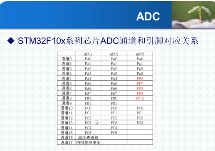
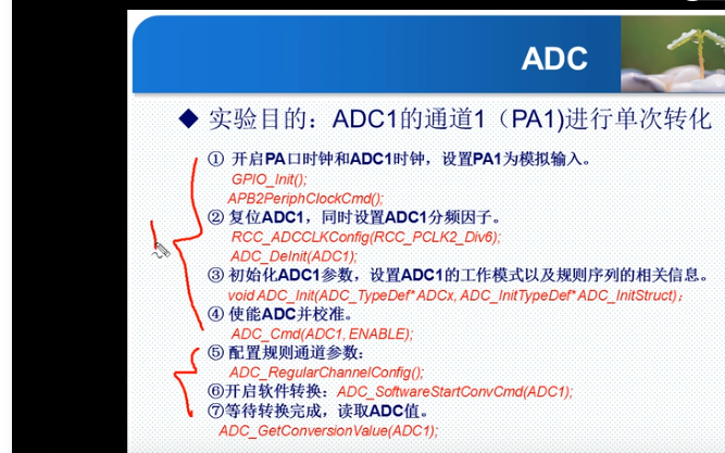
(2)AD的使用
------------恢复内容结束------------
任务