一、说明
在第一个程序里面,我们只是将图像上下左右平移,使用的矩阵也只有两个参数。
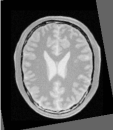
但是在下面的两幅图像里,不仅要旋转,还有平移变换,所选取的变换模型也不一样。

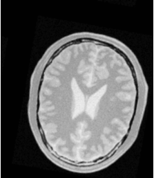
参考图像 待配准图像
这个时候我们选取的变换也更改为了欧拉二维变换矩阵
二、程序构建
找到例程里面的ImageRegistration5.cxx,按照之前的方法构建工程
程序我贴在这里:


/*=========================================================================
 *
 *  Copyright Insight Software Consortium
 *
 *  Licensed under the Apache License, Version 2.0 (the "License");
 *  you may not use this file except in compliance with the License.
 *  You may obtain a copy of the License at
 *
 *         http://www.apache.org/licenses/LICENSE-2.0.txt
 *
 *  Unless required by applicable law or agreed to in writing, software
 *  distributed under the License is distributed on an "AS IS" BASIS,
 *  WITHOUT WARRANTIES OR CONDITIONS OF ANY KIND, either express or implied.
 *  See the License for the specific language governing permissions and
 *  limitations under the License.
 *
 *=========================================================================*/

 //  Software Guide : BeginCommandLineArgs
 //    INPUTS:  {BrainProtonDensitySliceBorder20.png}
 //    INPUTS:  {BrainProtonDensitySliceRotated10.png}
 //    OUTPUTS: {ImageRegistration5Output.png}
 //    OUTPUTS: {ImageRegistration5DifferenceAfter.png}
 //    OUTPUTS: {ImageRegistration5DifferenceBefore.png}
 //    ARGUMENTS:    0.1
 //  Software Guide : EndCommandLineArgs

 //  Software Guide : BeginCommandLineArgs
 //    INPUTS:  {BrainProtonDensitySliceBorder20.png}
 //    INPUTS:  {BrainProtonDensitySliceR10X13Y17.png}
 //    OUTPUTS: {ImageRegistration5Output2.png}
 //    OUTPUTS: {ImageRegistration5DifferenceAfter2.png}
 //    OUTPUTS: {ImageRegistration5DifferenceBefore2.png}
 //    ARGUMENTS:    1.0
 //  Software Guide : EndCommandLineArgs


 // Software Guide : BeginLatex
 //
 // This example illustrates the use of the \doxygen{Euler2DTransform}
 // for performing rigid registration in $2D$. The example code is for the
 // most part identical to that presented in Section
 // \ref{sec:IntroductionImageRegistration}.  The main difference is the use
 // of the Euler2DTransform here instead of the
 // \doxygen{TranslationTransform}.
 //
 // \index{itk::Euler2DTransform}
 //
 // Software Guide : EndLatex

#include "itkImageRegistrationMethodv4.h"
#include "itkMeanSquaresImageToImageMetricv4.h"
#include "itkRegularStepGradientDescentOptimizerv4.h"


//  Software Guide : BeginLatex
//
//  In addition to the headers included in previous examples, the
//  following header must also be included.
//
//  \index{itk::Euler2DTransform!header}
//
//  Software Guide : EndLatex

// Software Guide : BeginCodeSnippet
#include "itkEuler2DTransform.h"
// Software Guide : EndCodeSnippet


#include "itkImageFileReader.h"
#include "itkImageFileWriter.h"

#include "itkResampleImageFilter.h"
#include "itkSubtractImageFilter.h"
#include "itkRescaleIntensityImageFilter.h"
#include "itkPNGImageIOFactory.h"

//  The following section of code implements a Command observer
//  that will monitor the evolution of the registration process.
//
#include "itkCommand.h"
class CommandIterationUpdate : public itk::Command
{
public:
    using Self = CommandIterationUpdate;
    using Superclass = itk::Command;
    using Pointer = itk::SmartPointer<Self>;
    itkNewMacro(Self);

protected:
    CommandIterationUpdate() = default;

public:
    using OptimizerType = itk::RegularStepGradientDescentOptimizerv4<double>;
    using OptimizerPointer = const OptimizerType*;

    void Execute(itk::Object* caller, const itk::EventObject& event) override
    {
        Execute((const itk::Object*)caller, event);
    }

    void Execute(const itk::Object* object, const itk::EventObject& event) override
    {
        auto optimizer = static_cast<OptimizerPointer>(object);
        if (!itk::IterationEvent().CheckEvent(&event))
        {
            return;
        }
        std::cout << optimizer->GetCurrentIteration() << "   ";
        std::cout << optimizer->GetValue() << "   ";
        std::cout << optimizer->GetCurrentPosition() << std::endl;
    }
};

int main(int argc, char* argv[])
{
    if (argc < 4)
    {
        std::cerr << "Missing Parameters " << std::endl;
        std::cerr << "Usage: " << argv[0];
        std::cerr << " fixedImageFile  movingImageFile ";
        std::cerr << " outputImagefile  [differenceAfterRegistration] ";
        std::cerr << " [differenceBeforeRegistration] ";
        std::cerr << " [initialStepLength] " << std::endl;
        return EXIT_FAILURE;
    }

    constexpr unsigned int Dimension = 2;
    using PixelType = float;

    using FixedImageType = itk::Image< PixelType, Dimension >;
    using MovingImageType = itk::Image< PixelType, Dimension >;


    //  Software Guide : BeginLatex
    //
    //  The transform type is instantiated using the code below. The only
    //  template parameter for this class is the representation type of the
    //  space coordinates.
    //
    //  \index{itk::Euler2DTransform!Instantiation}
    //
    //  Software Guide : EndLatex

    // Software Guide : BeginCodeSnippet
    using TransformType = itk::Euler2DTransform< double >;
    // Software Guide : EndCodeSnippet


    using OptimizerType = itk::RegularStepGradientDescentOptimizerv4<double>;
    using MetricType = itk::MeanSquaresImageToImageMetricv4<
        FixedImageType,
        MovingImageType >;
    using RegistrationType = itk::ImageRegistrationMethodv4<
        FixedImageType,
        MovingImageType,
        TransformType >;

    MetricType::Pointer         metric = MetricType::New();
    OptimizerType::Pointer      optimizer = OptimizerType::New();
    RegistrationType::Pointer   registration = RegistrationType::New();

    registration->SetMetric(metric);
    registration->SetOptimizer(optimizer);


    //  Software Guide : BeginLatex
    //
    //  In the Hello World! example, we used Fixed/Moving initial transforms
    //  to initialize the registration configuration. That approach was good to
    //  get an intuition of the registration method, specifically when we aim to run
    //  a multistage registration process, from which the output of each stage can
    //  be used to initialize the next registration stage.
    //
    //  To get a better underestanding of the registration process in
    //  such situations, consider an example of 3 stages registration process
    //  that is started using an initial moving transform ($\Gamma_{mi}$).
    //  Multiple stages are handled by linking multiple instantiations of
    //  the \doxygen{ImageRegistrationMethodv4} class.
    //  Inside the registration filter of the first stage, the initial moving
    //  transform is added to an internal composite transform along with an updatable
    //  identity transform ($\Gamma_{u}$). Although the whole composite transform
    //  is used for metric evaluation, only the $\Gamma_{u}$ is set to be updated
    //  by the optimizer at each iteration. The $\Gamma_{u}$ will be considered as
    //  the output transform of the current stage when the optimization process is
    //  converged. This implies that the output of this stage does not include
    //  the initialization parameters, so we need to concatenate the output and the
    //  initialization transform into a composite transform to be considered as the
    //  final transform of the first registration stage.
    //
    //  $ T_{1}(x) = \Gamma_{mi}(\Gamma_{stage_1}(x) ) $
    //
    //  Consider that, as explained in section \ref{sec:FeaturesOfTheRegistrationFramework},
    //  the above transform is a mapping from the vitual domain (i.e. fixed image space, when no
    //  fixed initial transform) to the moving image space.
    //
    //  Then, the result transform of the first stage will be used as the initial moving
    //  transform for the second stage of the registration process, and this approach goes on
    //  until the last stage of the registration process.
    //
    //  At the end of the registration process, the $\Gamma_{mi}$ and the outputs of each stage
    //  can be concatenated into a final composite transform that is considered to be the final
    //  output of the whole registration process.
    //
    //  $I'_{m}(x) = I_{m}(\Gamma_{mi}(\Gamma_{stage_1}(\Gamma_{stage_2}(\Gamma_{stage_3}(x) ) ) ) )$
    //
    //  The above approach is especially useful if individual stages are characterized by
    //  different types of transforms, e.g.  when we run a rigid registration
    //  process that is proceeded by an affine registration which is completed by a BSpline
    //  registration at the end.
    //
    //
    //  In addition to the above method, there is also a direct initialization method in which the
    //  initial transform will be optimized directly. In this way the initial transform will be
    //  modified during the registration process, so it can be used as the final transform when
    //  the registration process is completed. This direct approach is conceptually close to
    //  what was happening in ITKv3 registration.
    //
    //  Using this method is very simple and efficient when we have only one level of
    //  registration, which is the case in this example.
    //  Also, a good application of this initialization method in a multi-stage scenario
    //  is when two consequent stages have the same transform types, or at least the initial
    //  parameters can easily be inferred from the result of the previous stage, such as when a
    //  translation transform is followed by a rigid transform.
    //
    //  The direct initialization approach is shown by the current example in which we try
    //  to initialize the parameters of the optimizable transform ($\Gamma_{u}$) directly.
    //
    //  For this purpose, first, the initial transform object is constructed below.
    //  This transform will be initialized, and its initial parameters will be
    //  used when the registration process starts.
    //
    //  \index{itk::Euler2DTransform!New()}
    //  \index{itk::Euler2DTransform!Pointer}
    //
    //  Software Guide : EndLatex

    // Software Guide : BeginCodeSnippet
    TransformType::Pointer initialTransform = TransformType::New();
    // Software Guide : EndCodeSnippet


    using FixedImageReaderType = itk::ImageFileReader< FixedImageType  >;
    using MovingImageReaderType = itk::ImageFileReader< MovingImageType >;

    FixedImageReaderType::Pointer  fixedImageReader = FixedImageReaderType::New();
    MovingImageReaderType::Pointer movingImageReader = MovingImageReaderType::New();
    itk::PNGImageIOFactory::RegisterOneFactory();
    //    INPUTS:  {BrainProtonDensitySliceBorder20.png}
    //    INPUTS:  {BrainProtonDensitySliceR10X13Y17.png}
    fixedImageReader->SetFileName("D:\\Files\\ITKFiles\\ITK_8_RigidRegistration\\Data\\BrainProtonDensitySliceBorder20.png");
    movingImageReader->SetFileName("D:\\Files\\ITKFiles\\ITK_8_RigidRegistration\\Data\\BrainProtonDensitySliceR10X13Y17.png");


    registration->SetFixedImage(fixedImageReader->GetOutput());
    registration->SetMovingImage(movingImageReader->GetOutput());


    //  Software Guide : BeginLatex
    //
    //  In this example, the input images are taken from readers. The code
    //  below updates the readers in order to ensure that the image parameters
    //  (size, origin and spacing) are valid when used to initialize the
    //  transform.  We intend to use the center of the fixed image as the
    //  rotation center and then use the vector between the fixed image center
    //  and the moving image center as the initial translation to be applied
    //  after the rotation.
    //  将参考图像的中心作为旋转中心,然后使用参考图像与待配准图像的中心形成的向量作为初始化矩阵
    //  Software Guide : EndLatex

    // Software Guide : BeginCodeSnippet
    fixedImageReader->Update();
    movingImageReader->Update();
    // Software Guide : EndCodeSnippet

    using SpacingType = FixedImageType::SpacingType;
    using OriginType = FixedImageType::PointType;
    using RegionType = FixedImageType::RegionType;
    using SizeType = FixedImageType::SizeType;

    //  Software Guide : BeginLatex
    //
    //  The center of rotation is computed using the origin, size and spacing of
    //  the fixed image.
    //
    //  Software Guide : EndLatex

    // Software Guide : BeginCodeSnippet
    FixedImageType::Pointer fixedImage = fixedImageReader->GetOutput();

    const SpacingType fixedSpacing = fixedImage->GetSpacing();
    const OriginType  fixedOrigin = fixedImage->GetOrigin();
    const RegionType  fixedRegion = fixedImage->GetLargestPossibleRegion();
    const SizeType    fixedSize = fixedRegion.GetSize();

    TransformType::InputPointType centerFixed;

    //参考图像中心
    centerFixed[0] = fixedOrigin[0] + fixedSpacing[0] * fixedSize[0] / 2.0;
    centerFixed[1] = fixedOrigin[1] + fixedSpacing[1] * fixedSize[1] / 2.0;
    // Software Guide : EndCodeSnippet


    //  Software Guide : BeginLatex
    //  计算待配准图像的中心
    //  The center of the moving image is computed in a similar way.
    //
    //  Software Guide : EndLatex

    // Software Guide : BeginCodeSnippet
    MovingImageType::Pointer movingImage = movingImageReader->GetOutput();

    const SpacingType movingSpacing = movingImage->GetSpacing();
    const OriginType  movingOrigin = movingImage->GetOrigin();
    const RegionType  movingRegion = movingImage->GetLargestPossibleRegion();
    const SizeType    movingSize = movingRegion.GetSize();

    TransformType::InputPointType centerMoving;

    centerMoving[0] = movingOrigin[0] + movingSpacing[0] * movingSize[0] / 2.0;
    centerMoving[1] = movingOrigin[1] + movingSpacing[1] * movingSize[1] / 2.0;
    // Software Guide : EndCodeSnippet


    //  Software Guide : BeginLatex
    //
    //   Then, we initialize the transform by
    //   passing the center of the fixed image as the rotation center with the
    //   \code{SetCenter()} method. Also, the translation is set as the vector
    //   relating the center of the moving image to the center of the fixed
    //   image.  This last vector is passed with the method
    //   \code{SetTranslation()}.
    //   设置参考图像的中心作为旋转中心,平移是被设为与两个图像中心相关的的向量
    //  Software Guide : EndLatex

    // Software Guide : BeginCodeSnippet
    initialTransform->SetCenter(centerFixed);
    initialTransform->SetTranslation(centerMoving - centerFixed);
    // Software Guide : EndCodeSnippet


    //  Software Guide : BeginLatex
    //
    //  Let's finally initialize the rotation with a zero angle.
    //
    //  Software Guide : EndLatex

    // Software Guide : BeginCodeSnippet
    initialTransform->SetAngle(0.0);
    // Software Guide : EndCodeSnippet


    //  Software Guide : BeginLatex
    //  将矩阵传入配准方法
    //  Now the current parameters of the initial transform will be set
    //  to a registration method, so they can be assigned to the $\Gamma_{u}$ directly.
    //  Note that you should not confuse the following function with the
    //  \code{SetMoving(Fixed)InitialTransform()} methods that were used in Hello World! example.
    //
    //  Software Guide : EndLatex

    // Software Guide : BeginCodeSnippet
    registration->SetInitialTransform(initialTransform);
    // Software Guide : EndCodeSnippet

    //  Software Guide : BeginLatex
    //  注意旋转与平移的单位比例是不一样的,一个是rad,一个是mm
    //  我们需要参数比例去定制学习速率,与平移有关的比例我们选的小,
    //  实际上有一个函数可以自适应估计参数比例,在这个章节:MultiStageRegistration
    //  Keep in mind that the scale of units in rotation and translation is
    //  quite different. For example, here we know that the first element of the
    //  parameters array corresponds to the angle that is measured in radians, while
    //  the other parameters correspond to the translations that are measured in millimeters,
    //  so a naive application of gradient descent optimizer will not produce a smooth
    //  change of parameters, because a similar change of $\delta$
    //  to each parameter will produce a different magnitude of impact on the transform.
    //  As the result, we need ``parameter scales'' to customize the learning rate for
    //  each parameter. We can take advantage of the scaling functionality provided
    //  by the optimizers.
    //
    //  In this example we use small factors in the scales associated with
    //  translations. However, for the transforms with larger parameters
    //  sets, it is not intuitive for a user to  set the
    //  scales. Fortunately, a framework for automated estimation of
    //  parameter scales is provided by ITKv4 that will be discussed
    //  later in the example of section \ref{sec:MultiStageRegistration}.
    //
    //  Software Guide : EndLatex

    // Software Guide : BeginCodeSnippet
    using OptimizerScalesType = OptimizerType::ScalesType;
    OptimizerScalesType optimizerScales(
        initialTransform->GetNumberOfParameters());
    const double translationScale = 1.0 / 1000.0;

    optimizerScales[0] = 1.0;
    optimizerScales[1] = translationScale;
    optimizerScales[2] = translationScale;

    optimizer->SetScales(optimizerScales);
    // Software Guide : EndCodeSnippet


    //  Software Guide : BeginLatex
    //  我们使用梯度下降优化器,设置松弛系数,学习速率,最小步长,迭代次数(后两个是停止条件)。
    //  Next we set the normal parameters of the optimization method. In this
    //  case we are using an \doxygen{RegularStepGradientDescentOptimizerv4}.
    //  Below, we define the optimization parameters like the relaxation factor,
    //  learning rate (initial step length), minimal step length and number of
    //  iterations. These last two act as stopping criteria for the optimization.
    //
    //  \index{Regular\-Step\-Gradient\-Descent\-Optimizer!SetRelaxationFactor()}
    //  \index{Regular\-Step\-Gradient\-Descent\-Optimizer!SetLearningRate()}
    //  \index{Regular\-Step\-Gradient\-Descent\-Optimizer!SetMinimumStepLength()}
    //  \index{Regular\-Step\-Gradient\-Descent\-Optimizer!SetNumberOfIterations()}
    //
    //  Software Guide : EndLatex

    // Software Guide : BeginCodeSnippet
    double initialStepLength = 1.3;//0.1;
    // Software Guide : EndCodeSnippet

    if (argc > 6)
    {
        initialStepLength = std::stod(argv[6]);
    }

    // Software Guide : BeginCodeSnippet
    optimizer->SetRelaxationFactor(0.6);
    optimizer->SetLearningRate(initialStepLength);
    optimizer->SetMinimumStepLength(0.001);
    optimizer->SetNumberOfIterations(200);

    // Software Guide : EndCodeSnippet
    //optimizer->SetMaximumStepLength(1.3);

    // Create the Command observer and register it with the optimizer.
    // 将observer和optimizer连接起来
    CommandIterationUpdate::Pointer observer = CommandIterationUpdate::New();
    optimizer->AddObserver(itk::IterationEvent(), observer);

    // One level registration process without shrinking and smoothing.
    // 无缩小和光滑的一层配准
    constexpr unsigned int numberOfLevels = 1;

    RegistrationType::ShrinkFactorsArrayType shrinkFactorsPerLevel;
    shrinkFactorsPerLevel.SetSize(1);
    shrinkFactorsPerLevel[0] = 1;

    RegistrationType::SmoothingSigmasArrayType smoothingSigmasPerLevel;
    smoothingSigmasPerLevel.SetSize(1);
    smoothingSigmasPerLevel[0] = 0;

    registration->SetNumberOfLevels(numberOfLevels);
    registration->SetSmoothingSigmasPerLevel(smoothingSigmasPerLevel);
    registration->SetShrinkFactorsPerLevel(shrinkFactorsPerLevel);

    try
    {
        registration->Update();
        std::cout << "Optimizer stop condition: "
            << registration->GetOptimizer()->GetStopConditionDescription()
            << std::endl;
    }
    catch (itk::ExceptionObject& err)
    {
        std::cerr << "ExceptionObject caught !" << std::endl;
        std::cerr << err << std::endl;
        return EXIT_FAILURE;
    }

    const TransformType::ParametersType finalParameters =
        registration->GetOutput()->Get()->GetParameters();

    const double finalAngle = finalParameters[0];
    const double finalTranslationX = finalParameters[1];
    const double finalTranslationY = finalParameters[2];

    const double rotationCenterX = registration->GetOutput()->Get()->GetCenter()[0];
    const double rotationCenterY = registration->GetOutput()->Get()->GetCenter()[1];

    const unsigned int numberOfIterations = optimizer->GetCurrentIteration();

    const double bestValue = optimizer->GetValue();


    // Print out results
    //
    const double finalAngleInDegrees = finalAngle * 180.0 / itk::Math::pi;

    std::cout << "Result = " << std::endl;
    std::cout << " Angle (radians) = " << finalAngle << std::endl;
    std::cout << " Angle (degrees) = " << finalAngleInDegrees << std::endl;
    std::cout << " Translation X   = " << finalTranslationX << std::endl;
    std::cout << " Translation Y   = " << finalTranslationY << std::endl;
    std::cout << " Fixed Center X  = " << rotationCenterX << std::endl;
    std::cout << " Fixed Center Y  = " << rotationCenterY << std::endl;
    std::cout << " Iterations      = " << numberOfIterations << std::endl;
    std::cout << " Metric value    = " << bestValue << std::endl;


    //  Software Guide : BeginLatex
    //
    //  Let's execute this example over two of the images provided in
    //  \code{Examples/Data}:
    //
    //  \begin{itemize}
    //  \item \code{BrainProtonDensitySliceBorder20.png}
    //  \item \code{BrainProtonDensitySliceRotated10.png}
    //  \end{itemize}
    //
    //  The second image is the result of intentionally rotating the first image
    //  by $10$ degrees around the geometrical center of the image. Both images
    //  have unit-spacing and are shown in Figure
    //  \ref{fig:FixedMovingImageRegistration5}. The registration takes $17$
    //  iterations and produces the results:
    //
    //  \begin{center}
    //  \begin{verbatim}
    //  [0.177612, 0.00681015, 0.00396471]//第一个是弧度制的角度,第二个是mm
    //  \end{verbatim}
    //  \end{center}
    //
    //  These results are interpreted as
    //
    //  \begin{itemize}
    //  \item Angle         =                  $0.177612$     radians
    //  \item Translation   = $( 0.00681015, 0.00396471 )$ millimeters
    //  \end{itemize}
    //
    //  As expected, these values match the misalignment intentionally introduced
    //  into the moving image quite well, since $10$ degrees is about $0.174532$
    //  radians.
    //
    // \begin{figure}
    // \center
    // \includegraphics[width=0.44\textwidth]{BrainProtonDensitySliceBorder20}
    // \includegraphics[width=0.44\textwidth]{BrainProtonDensitySliceRotated10}
    // \itkcaption[Rigid2D Registration input images]{Fixed and moving images
    // are provided as input to the registration method using the CenteredRigid2D
    // transform.}
    // \label{fig:FixedMovingImageRegistration5}
    // \end{figure}
    //
    //
    // \begin{figure}
    // \center
    // \includegraphics[width=0.32\textwidth]{ImageRegistration5Output}
    // \includegraphics[width=0.32\textwidth]{ImageRegistration5DifferenceBefore}
    // \includegraphics[width=0.32\textwidth]{ImageRegistration5DifferenceAfter}
    // \itkcaption[Rigid2D Registration output images]{Resampled moving image
    // (left). Differences between the fixed and moving images, before (center)
    // and after (right) registration using the Euler2D transform.}
    // \label{fig:ImageRegistration5Outputs}
    // \end{figure}
    //
    // Figure \ref{fig:ImageRegistration5Outputs} shows from left to right the
    // resampled moving image after registration, the difference between the fixed
    // and moving images before registration, and the difference between the fixed
    // and resampled moving image after registration. It can be seen from the
    // last difference image that the rotational component has been solved but
    // that a small centering misalignment persists.
    //
    // \begin{figure}
    // \center
    // \includegraphics[height=0.32\textwidth]{ImageRegistration5TraceMetric1}
    // \includegraphics[height=0.32\textwidth]{ImageRegistration5TraceAngle1}
    // \includegraphics[height=0.32\textwidth]{ImageRegistration5TraceTranslations1}
    // \itkcaption[Rigid2D Registration output plots]{Metric values, rotation
    // angle and translations during registration with the Euler2D
    // transform.}
    // \label{fig:ImageRegistration5Plots}
    // \end{figure}
    //
    //  Figure \ref{fig:ImageRegistration5Plots} shows plots of the main output
    //  parameters produced from the registration process. This includes the
    //  metric values at every iteration, the angle values at every iteration,
    //  and the translation components of the transform as the registration
    //  progresses.
    //
    //  Software Guide : EndLatex


    using ResampleFilterType = itk::ResampleImageFilter<
        MovingImageType,
        FixedImageType >;

    //TransformType::ConstPointer finalTransform = TransformType::New();

    //TransformType::ConstPointer finalTransform = registration->GetTransform();

    ResampleFilterType::Pointer resample = ResampleFilterType::New();

    //这里是用来验证图像的坐标轴的
    //centerMoving[0] = 40;
    //centerMoving[1] = 40;
    //centerFixed[0] = 0;
    //centerFixed[1] = 0;
    //initialTransform->SetTranslation(centerMoving - centerFixed);
    //resample->SetTransform(initialTransform);

    resample->SetTransform(registration->GetTransform());

    resample->SetInput(movingImageReader->GetOutput());

    resample->SetSize(fixedImage->GetLargestPossibleRegion().GetSize());
    resample->SetOutputOrigin(fixedImage->GetOrigin());
    resample->SetOutputSpacing(fixedImage->GetSpacing());
    resample->SetOutputDirection(fixedImage->GetDirection());
    resample->SetDefaultPixelValue(100);

    using OutputPixelType = unsigned char;
    using OutputImageType = itk::Image< OutputPixelType, Dimension >;
    using CastFilterType = itk::CastImageFilter<
        FixedImageType,
        OutputImageType >;
    using WriterType = itk::ImageFileWriter< OutputImageType >;

    WriterType::Pointer      writer = WriterType::New();
    CastFilterType::Pointer  caster = CastFilterType::New();

    writer->SetFileName("D:\\Files\\ITKFiles\\ITK_8_RigidRegistration\\Data\\ResampledMovingImage.png");

    caster->SetInput(resample->GetOutput());
    writer->SetInput(caster->GetOutput());

    try
    {
        writer->Update();
    }
    catch (itk::ExceptionObject& excp)
    {
        std::cerr << "ExceptionObject while writing the resampled image !" << std::endl;
        std::cerr << excp << std::endl;
        return EXIT_FAILURE;
    }

    using DifferenceImageType = itk::Image< float, Dimension >;

    using DifferenceFilterType = itk::SubtractImageFilter<
        FixedImageType,
        FixedImageType,
        DifferenceImageType >;

    DifferenceFilterType::Pointer difference = DifferenceFilterType::New();

    using RescalerType = itk::RescaleIntensityImageFilter<
        DifferenceImageType,
        OutputImageType >;

    RescalerType::Pointer intensityRescaler = RescalerType::New();

    intensityRescaler->SetOutputMinimum(0);
    intensityRescaler->SetOutputMaximum(255);

    difference->SetInput1(fixedImageReader->GetOutput());
    difference->SetInput2(resample->GetOutput());

    resample->SetDefaultPixelValue(1);

    intensityRescaler->SetInput(difference->GetOutput());

    WriterType::Pointer      writer2 = WriterType::New();

    writer2->SetInput(intensityRescaler->GetOutput());


    try
    {
        // Compute the difference image between the
        // fixed and moving image after registration.
        if (argc > 4)
        {
            writer2->SetFileName("D:\\Files\\ITKFiles\\ITK_8_RigidRegistration\\Data\\DifferenceBefore.png");
            writer2->Update();
        }

        // Compute the difference image between the
        // fixed and resampled moving image after registration.
        TransformType::Pointer identityTransform = TransformType::New();
        identityTransform->SetIdentity();
        resample->SetTransform(identityTransform);
        if (argc > 5)
        {
            writer2->SetFileName("D:\\Files\\ITKFiles\\ITK_8_RigidRegistration\\Data\\DifferenceAfter.png");
            writer2->Update();
        }
    }
    catch (itk::ExceptionObject& excp)
    {
        std::cerr << "Error while writing difference images" << std::endl;
        std::cerr << excp << std::endl;
        return EXIT_FAILURE;
    }

    //  Software Guide : BeginLatex
    //
    //  Let's now consider the case in which rotations and translations are
    //  present in the initial registration, as in the following pair
    //  of images:
    //
    //  \begin{itemize}
    //  \item \code{BrainProtonDensitySliceBorder20.png}
    //  \item \code{BrainProtonDensitySliceR10X13Y17.png}
    //  \end{itemize}
    //
    //  The second image is the result of intentionally rotating the first image
    //  by $10$ degrees and then translating it $13mm$ in $X$ and $17mm$ in $Y$.
    //  Both images have unit-spacing and are shown in Figure
    //  \ref{fig:FixedMovingImageRegistration5b}. In order to accelerate
    //  convergence it is convenient to use a larger step length as shown here.
    //  为了加快融合应该设置一个更大的步长
    //  \code{optimizer->SetMaximumStepLength( 1.3 );}
    //
    //  The registration now takes $37$ iterations and produces the following
    //  results:
    //
    //  \begin{center}
    //  \begin{verbatim}
    //  [0.174582, 13.0002, 16.0007]
    //  \end{verbatim}
    //  \end{center}
    //
    //  These parameters are interpreted as
    //
    //  \begin{itemize}
    //  \item Angle         =                     $0.174582$   radians
    //  \item Translation   = $( 13.0002,  16.0007 )$ millimeters
    //  \end{itemize}
    //
    //  These values approximately match the initial misalignment intentionally
    //  introduced into the moving image, since $10$ degrees is about $0.174532$
    //  radians. The horizontal translation is well resolved while the vertical
    //  translation ends up being off by about one millimeter.
    //
    // \begin{figure}
    // \center
    // \includegraphics[width=0.44\textwidth]{BrainProtonDensitySliceBorder20}
    // \includegraphics[width=0.44\textwidth]{BrainProtonDensitySliceR10X13Y17}
    // \itkcaption[Rigid2D Registration input images]{Fixed and moving images
    // provided as input to the registration method using the CenteredRigid2D
    // transform.}
    // \label{fig:FixedMovingImageRegistration5b}
    // \end{figure}
    //
    //
    // \begin{figure}
    // \center
    // \includegraphics[width=0.32\textwidth]{ImageRegistration5Output2}
    // \includegraphics[width=0.32\textwidth]{ImageRegistration5DifferenceBefore2}
    // \includegraphics[width=0.32\textwidth]{ImageRegistration5DifferenceAfter2}
    // \itkcaption[Rigid2D Registration output images]{Resampled moving image
    // (left). Differences between the fixed and moving images, before (center)
    // and after (right) registration with the CenteredRigid2D transform.}
    // \label{fig:ImageRegistration5Outputs2}
    // \end{figure}
    //
    // Figure \ref{fig:ImageRegistration5Outputs2} shows the output of the
    // registration. The rightmost image of this figure shows the difference
    // between the fixed image and the resampled moving image after registration.
    //
    // \begin{figure}
    // \center
    // \includegraphics[height=0.32\textwidth]{ImageRegistration5TraceMetric2}
    // \includegraphics[height=0.32\textwidth]{ImageRegistration5TraceAngle2}
    // \includegraphics[height=0.32\textwidth]{ImageRegistration5TraceTranslations2}
    // \itkcaption[Rigid2D Registration output plots]{Metric values, rotation
    // angle and translations during the registration using the Euler2D
    // transform on an image with rotation and translation mis-registration.}
    // \label{fig:ImageRegistration5Plots2}
    // \end{figure}
    //
    //  Figure \ref{fig:ImageRegistration5Plots2} shows plots of the main output
    //  registration parameters when the rotation and translations are combined.
    //  These results include the metric values at every iteration, the angle
    //  values at every iteration, and the translation components of the
    //  registration as the registration converges. It can be seen from the
    //  smoothness of these plots that a larger step length could have been
    //  supported easily by the optimizer. You may want to modify this value in
    //  order to get a better idea of how to tune the parameters.
    //
    //  Software Guide : EndLatex


    return EXIT_SUCCESS;
}
三、程序注意事项
这个程序和之前的程序有几点不同:
1-这里设置的矩阵和之前不一样,在Helloworld 程序里面的矩阵,包括两个初始化矩阵,那是适用于多层配准的一般方法的,而我们如今定义的这种方式要更加直接。
2-图像的输入和输出参数在注释中已经有了(输入图片在toolkit/Examples/Data里面),所以要注意,这里我使用的是第二组图片:
 //    INPUTS:  {BrainProtonDensitySliceBorder20.png}
 //    INPUTS:  {BrainProtonDensitySliceR10X13Y17.png}
 //    OUTPUTS: {ImageRegistration5Output2.png}
 //    OUTPUTS: {ImageRegistration5DifferenceAfter2.png}
 //    OUTPUTS: {ImageRegistration5DifferenceBefore2.png}
 //    ARGUMENTS:    1.0
3-我们在使用2中提到的图片的时候,需要修改配准的最小步长,使得它大一点,不然即使达到了最大的迭代次数,也达不到条件。
double initialStepLength = 1.3;//0.1;
我们可以在命令行第六个参数中设置为1.3
4-我们得到的矩阵如下:
    const TransformType::ParametersType finalParameters =
        registration->GetOutput()->Get()->GetParameters();

    const double finalAngle = finalParameters[0];
    const double finalTranslationX = finalParameters[1];
    const double finalTranslationY = finalParameters[2];
矩阵输出如下:
    std::cout << "Result = " << std::endl;
    std::cout << " Angle (radians) = " << finalAngle << std::endl;
    std::cout << " Angle (degrees) = " << finalAngleInDegrees << std::endl;
    std::cout << " Translation X   = " << finalTranslationX << std::endl;
    std::cout << " Translation Y   = " << finalTranslationY << std::endl;
输出:
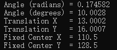
可以看到,矩阵的第一个参数是以弧度制表示的角度(rad),第二个和第三个则是位移(mm)
5- 我们的得到的图像,其原点位于左上方,水平方向为X轴,竖直方向为Y轴,如下:
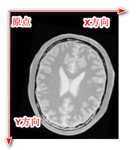
验证如下:
在写校正之后的文件的时候,当我们把597行的平移参数设置为如下代码的时候:
    //这里是用来验证图像的坐标轴的
    centerMoving[0] = 40;
    centerMoving[1] = 40;
    centerFixed[0] = 0;
    centerFixed[1] = 0;
    initialTransform->SetTranslation(centerMoving - centerFixed);
    resample->SetTransform(initialTransform);

    //resample->SetTransform(registration->GetTransform());
我们得到的图像相比如原来的来说:
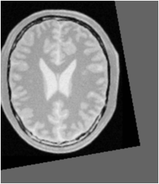
平移变大 原有图像
这个时候我们得到的图像相对于原来的来说,朝着左上角平移了一定距离。
所以上面猜想是正确的。
其他的具体情况可以参考指导书
四、参考
参考书籍:InsightSoftwareGuide-Book2-5.0.1 Registration-Center Initialization Page209
源码:ImageRegistration5.cxx