课上写全减器,题看错了,还以为是用生成语句把两个半减器和一个与门连成一个全减器。现在一看,原来是先生成一个全减器,再用原件例化生成8位全减器1.半减器
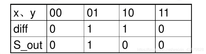
找到真值表:
代码:课上我是用两个with——select写的,忘记了vhdl也可以用数组的方式,注意with——select是直接放在结构体下的!
如果是给高阻态,一定大写的Z。
--ujs-lili
library IEEE;
use IEEE.STD_LOGIC_1164.ALL;
use IEEE.STD_LOGIC_unsigned.ALL;
entity sub_h_suber is
port(
  x,y:in std_logic;
  diff,s_out:out std_logic);
end sub_h_suber;
architecture Behavioral of sub_h_suber is
signal a,b: std_logic_vector(1 downto 0);
begin
 a<=x&y;
 with a select
 b<="00" when "00",
  "11" when "01",
  "10" when "10",
  "00" when "11",
  "ZZ" when others;  --大写的ZZ才可以!!!
 diff<=b(1);
 s_out<=b(0);
end Behavioral;


——仿真代码
LIBRARY ieee;
USE ieee.std_logic_1164.ALL;
ENTITY sub_h_suber_tb IS
END sub_h_suber_tb;
ARCHITECTURE behavior OF sub_h_suber_tb IS
    -- Component Declaration for the Unit Under Test (UUT)
    COMPONENT sub_h_suber
    PORT(
         x : IN  std_logic;
         y : IN  std_logic;
         diff : OUT  std_logic;
         s_out : OUT  std_logic
        );
    END COMPONENT;
   --Inputs
   signal x : std_logic := '0';
   signal y : std_logic := '0';
  --Outputs
   signal diff : std_logic;
   signal s_out : std_logic;
   -- No clocks detected in port list. Replace <clock> below with
   -- appropriate port name
BEGIN
 -- Instantiate the Unit Under Test (UUT)
   uut: sub_h_suber PORT MAP (
          x => x,
          y => y,
          diff => diff,
          s_out => s_out
        );
   -- Stimulus process
   stim_proc: process
   begin
   x<='0';y<='0';
      wait for 100 ns;
  x<='0';y<='1';
      wait for 100 ns;
  x<='1';y<='0';
      wait for 100 ns;
  x<='1';y<='1';
      wait for 100 ns;
   end process;
END;
做完别急,先仿真:
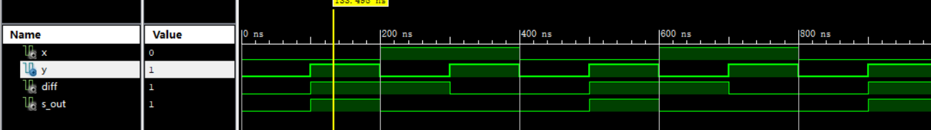
可以对照真值表看一下,对的!
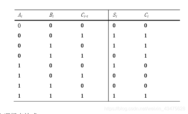
2.一位全加器
找到真值表,来做仿真用
代码:
--ujs-lili
library IEEE;
use IEEE.STD_LOGIC_1164.ALL;
use IEEE.STD_LOGIC_unsigned.ALL;
entity sub_top is
 port(x,y,sub_in:in std_logic ;
  diffr,sub_out:out std_logic);--out忘记写!!!
end sub_top;
architecture Behavioral of sub_top is
component sub_h_suber is
port(
  x,y:in std_logic;
  diff,s_out:out std_logic);
end component sub_h_suber;
signal a,b,c : std_logic;
begin
u1:sub_h_suber port map(x=>x,y=>y,diff=>a,s_out=>b);
u2:sub_h_suber port map(x=>a,y=>sub_in,diff=>diffr,s_out=>c);--这个地方是两个都用sub_h_suber,标号不一样就可以
sub_out<=c or b;
end Behavioral;


--仿真:
LIBRARY ieee;
USE ieee.std_logic_1164.ALL;
ENTITY sub_tb IS
END sub_tb;
ARCHITECTURE behavior OF sub_tb IS
    COMPONENT sub_top
    PORT(
         x : IN  std_logic;
         y : IN  std_logic;
         sub_in : IN  std_logic;
         diffr : OUT  std_logic;
         sub_out : OUT  std_logic
        );
    END COMPONENT;
   --Inputs
   signal x : std_logic := '0';
   signal y : std_logic := '0';
   signal sub_in : std_logic := '0';
  --Outputs
   signal diffr : std_logic;
   signal sub_out : std_logic;
BEGIN
   uut: sub_top PORT MAP (
          x => x,
          y => y,
          sub_in => sub_in,
          diffr => diffr,
          sub_out => sub_out
        );
   stim_proc: process
   begin
   x<='0';y<='0';sub_in<='0';
      wait for 100 ns;
   x<='0';y<='0';sub_in<='1';
      wait for 100 ns;
   x<='0';y<='1';sub_in<='0';
      wait for 100 ns;
   x<='0';y<='1';sub_in<='1';
      wait for 100 ns;
 x<='1';y<='0';sub_in<='0';
      wait for 100 ns;
   x<='1';y<='0';sub_in<='1';
      wait for 100 ns;
   x<='1';y<='1';sub_in<='0';
      wait for 100 ns;
   x<='1';y<='1';sub_in<='1';
      wait for 100 ns;
   end process;
END;
对照真值表看正确!

3.制作8位减法器,就是生成嘛!
注意点generate的port map之前一定要写原件名!!!
signal stmp:std_logic_vector(8 downto 0);
begin
stmp(0)<=sub_in;sub_out<=stmp(8);
会定义一个中间信号,9位的,第一位用来记录输入进位,最后一位记录输出进位,中间有7位进位是相互传递的,总的来说:外部给一个借位输入,先过第一个全减器,产生进位信号,给stmp,在传递给第二个全减器,那么这样过8个,很清楚,最后一个给sub_out
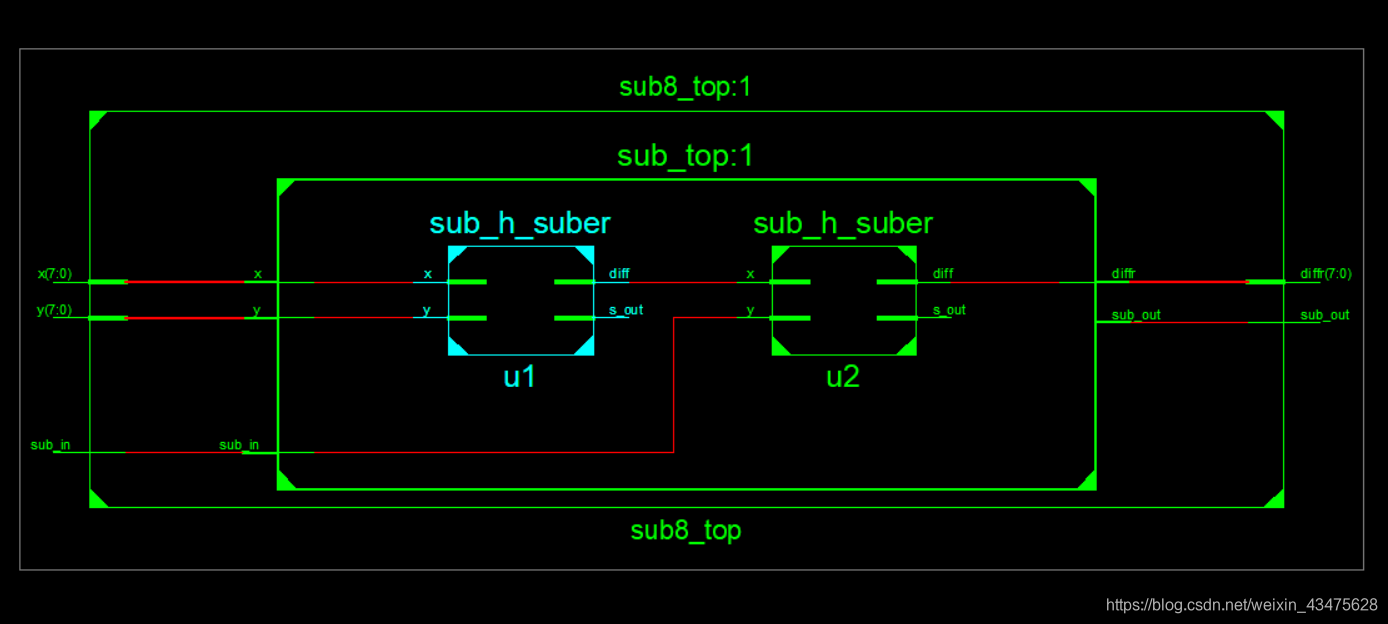
直接看原理图:
跟我想的不一样,我以为是8个sub串联那种,结果它给我总线形式:
代码:
--ujs-lili
library IEEE;
use IEEE.STD_LOGIC_1164.ALL;
entity sub8_top is
port(x,y:in std_logic_vector(7 downto 0);
 sub_in:in std_logic;
 diffr:out std_logic_vector(7 downto 0);
 sub_out:out std_logic);
end sub8_top;
architecture Behavioral of sub8_top is
component sub_top is
 port(x,y,sub_in:in std_logic ;
  diffr,sub_out:out std_logic);--out忘记写!!!
end component sub_top;
signal stmp:std_logic_vector(8 downto 0);
begin
stmp(0)<=sub_in;sub_out<=stmp(8);
gensub:for i in 0 to 7 generate
u1:sub_top port map(x(i),y(i),sub_in,diffr(i),stmp(i+1));
end generate;
end Behavioral;


__仿真,你要是不懂借位的意思,你把它当作一位的做好了,就前7位都是0

LIBRARY ieee;
USE ieee.std_logic_1164.ALL;
-- Uncomment the following library declaration if using
-- arithmetic functions with Signed or Unsigned values
--USE ieee.numeric_std.ALL;
ENTITY sub8_top_tb IS
END sub8_top_tb;
ARCHITECTURE behavior OF sub8_top_tb IS
    -- Component Declaration for the Unit Under Test (UUT)
    COMPONENT sub8_top
    PORT(
         x : IN  std_logic_vector(7 downto 0);
         y : IN  std_logic_vector(7 downto 0);
         sub_in : IN  std_logic;
         diffr : OUT  std_logic_vector(7 downto 0);
         sub_out : OUT  std_logic
        );
    END COMPONENT;
   --Inputs
   signal x : std_logic_vector(7 downto 0) := (others => '0');
   signal y : std_logic_vector(7 downto 0) := (others => '0');
   signal sub_in : std_logic := '0';
  --Outputs
   signal diffr : std_logic_vector(7 downto 0);
   signal sub_out : std_logic;
   -- No clocks detected in port list. Replace <clock> below with
   -- appropriate port name
BEGIN
 -- Instantiate the Unit Under Test (UUT)
   uut: sub8_top PORT MAP (
          x => x,
          y => y,
          sub_in => sub_in,
          diffr => diffr,
          sub_out => sub_out
        );
   -- Stimulus process
   stim_proc: process
   begin
     x<="00000001";y<="00000000";sub_in<='0';
      wait for 100 ns;
   x<="00000001";y<="00000000";sub_in<='0';
      wait for 100 ns;
    x<="00000001";y<="00000001";sub_in<='1';
      wait for 100 ns;
    x<="11111111";y<="11111110";sub_in<='0';
      wait for 100 ns;
 x<="00000000";y<="00000000";sub_in<='0';
      wait for 100 ns;
   x<="00000000";y<="00000000";sub_in<='1';
      wait for 100 ns;
   x<="00000000";y<="00000001";sub_in<='0';
      wait for 100 ns;
   x<="00000000";y<="00000001";sub_in<='1';
      wait for 100 ns;
   x<="00000001";y<="00000001";sub_in<='1';
      wait for 100 ns;
   end process;
END;
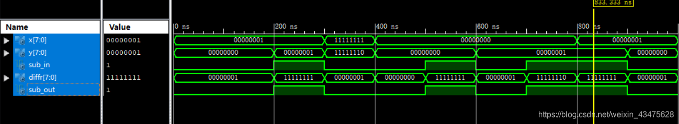
比如看:
x=00000001,y=00000001,sub_in=1,其实x-y=0,你再借个位变成11111111
然后要是不懂400ns之后看,这就跟1位全减器一个意思。
4.总结
半加器,一位全加器(根据原理图连接),生成八位全加器(注意中间9位的信号)
