前言
本部分实验基于电子森林小脚丫开发板的数电入门教程实验。实验链接:step-mxo2入门教程 电子森林] (eetree.cn)
其中代码是博主学习后根据自己思路自己敲的,并非直接复制,且仅供学习交流使用,侵删。
lattice 环境配置在此不再赘述~
按键LED
module LED (key,sw,led);
	input [3:0] key;
	input [3:0] sw;
	output [7:0] led;

	assign led={key, sw};

endmodule
三色LED
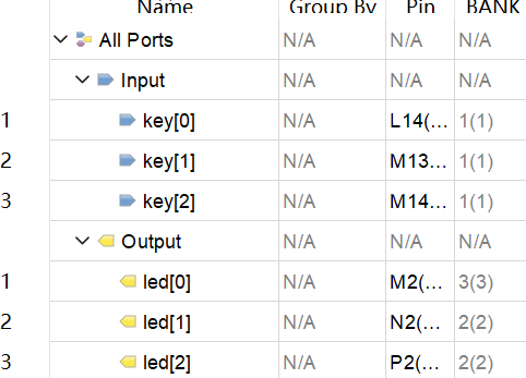
开发板上的一个三色LED灯,通过赋3位值来决定亮哪个颜色。用三个按键控制 easy
module LED (key,led);
	input [2:0] key;
	output [2:0] led;

	assign led={key};

endmodule
3-8译码器
三个按键输出8个状态。主要是练习 always case 的使用。
module LED (key,led);
	input [2:0] key;
	output [7:0] led;
	reg [7:0] led;
	always @(key)
	begin
		case(key)
			3'b000:led=8'b11111110;
			3'b001:led=8'b11111101;
			3'b010:led=8'b11111011;
			3'b011:led=8'b11110111;
			3'b100:led=8'b11101111;
			3'b101:led=8'b11011111;
			3'b110:led=8'b10111111;
			3'b111:led=8'b01111111;
			default:;
		endcase
	end


endmodule
数码管显示
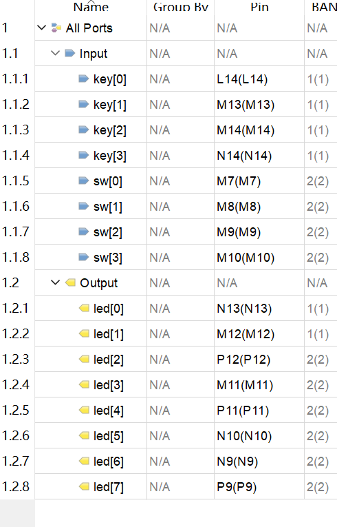
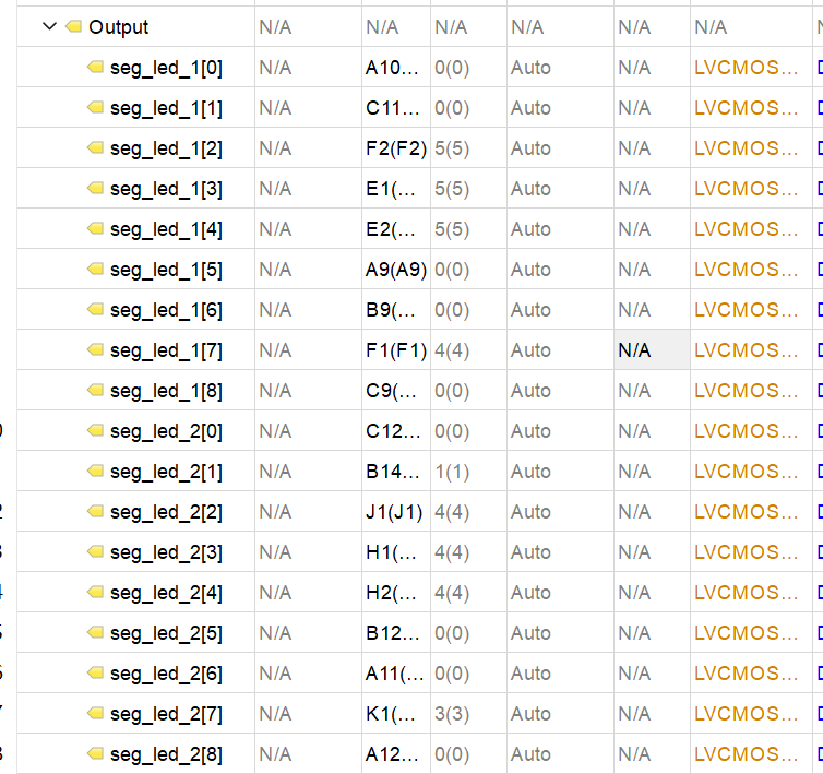
两个数码管,每个需要9位输入,其中4位是数据输入,可以输入10种状态对应0-9.
我们通过按键和拨码开关传入数据。led 设置我想就记住就行先。
module SEG_LED (key,sw,seg_led_1,seg_led_2);
	input [3:0] key;
	input  [3:0] sw;
	output [8:0] seg_led_1;
	output [8:0] seg_led_2;

	reg [8:0] seg [9:0];

	initial
	begin
		seg[0]=9'h3f;
		seg[1]=9'h06;
		seg[2]=9'h5b;
		seg[3]=9'h4f;
		seg[4]=9'h66;
		seg[5]=9'h6d;
		seg[6]=9'h7d;
		seg[7]=9'h07;
		seg[8]=9'h7f;
		seg[9]=9'h6f;
	end

	assign seg_led_1=seg[key];
	assign seg_led_2=seg[sw];


endmodule
时钟分频
算法
偶数倍频:光看上升或者下降沿个数就行,0N/2-1时翻转,N/2N-1时再翻转。
奇数倍频:形如下图。
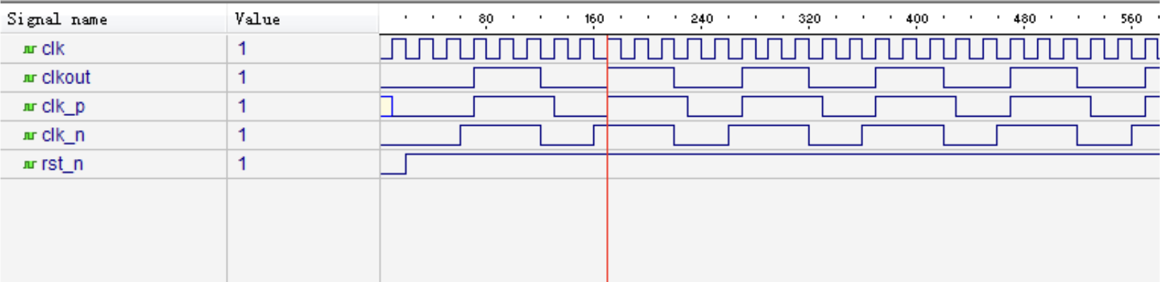
如图为5分频,输入5个周期输出1个周期。所以每2.5个周期一翻转,比如从上升沿开始,再经过两个上升沿,后一个下降沿后翻转。
这样就没法只通过上升或者下降沿去判断了,因为结尾是半个上升/下降沿。不过通过纯上升,下降沿的波形(上升沿比下降沿多一个周期)我们可以发现,两者and操作得到的就是我们想要的结果。
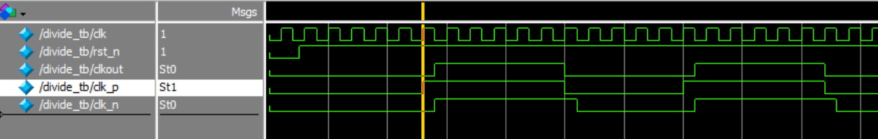
实现
module div(clk_in, rst_n ,clk_out);
	input clk_in,rst_n;
	output clk_out;

	parameter WIDTH=3;
	parameter N=5;

	reg [WIDTH-1:0] cnt_p, cnt_n;
	reg clk_p, clk_n;

	always @ (posedge clk_in or negedge rst_n)
		begin
			if(!rst_n)cnt_p<=0;
			else if(cnt_p==(N-1))
				cnt_p<=0;
			else
				cnt_p<=cnt_p+1;
		end

	always @ (negedge clk_in or negedge rst_n)
		begin
			if(!rst_n)cnt_n<=0;
			else if(cnt_n==(N-1))
				cnt_n<=0;
			else
				cnt_n<=cnt_n+1;
		end

	always @ (posedge clk_in or negedge rst_n)
		begin
			if(!rst_n)clk_p<=0;
			else if(cnt_p<(N>>1))
				clk_p<=0;
			else
				clk_p<=1;
		end

	always @ (negedge clk_in or negedge rst_n)
		begin
			if(!rst_n)clk_n<=0;
			else if(cnt_n<(N>>1))
				clk_n<=0;
			else
				clk_n<=1;
		end

	assign clk_out=(N==1)?clk_in:(N[0])?clk_p&clk_n:clk_p;
endmodule
打不开仿真显示 license 错误可能是仿真和 license 版本不对。
流水灯
采用模块的思想。我们把前面的3-8译码器(led)部分和时钟分频部分代码结合起来,然后用一个模块去用他俩,传递输入输出。
module flashled (clk,rst,led);
	input clk,rst;
	output [7:0]led;

	reg [2:0] cnt;

	wire clk1h;

	LED u1 (
		.key(cnt),
		.led(led)
	);

	div #(.WIDTH(32),.N(12000000)) u2 (
        .clk_in(clk),
        .rst_n(rst),
        .clk_out(clk1h)
    );

	always @(posedge clk1h or negedge rst)
		if(!rst)
			cnt<=0;
		else
			cnt<=cnt+1;
endmodule
还有一种简单的 led 赋值法,我们知道 led 形如 1111 1101 也就是8位不断循环来形成流水灯的效果。所以我们只需要让 led 不断循环左移或者右移就行。
led={led[0],led[7:1]};
按键消抖
如果只是一个简单的按下按键翻转LED灯状态,那确实很好写:
module debounce (key,rst,key_pulse);
	input key,rst;
	output key_pulse;

	reg key_pulse;

	always @(negedge rst or negedge key)
		begin
			if(!rst)
				key_pulse=1;
			else
				key_pulse=~key_pulse;
		end

endmodule
选用一个按键作为 rst,一个按键为 led 的输入。
但是经典问题,按下按键和松开的一瞬间按键的电平是不断抖动的并不稳定:
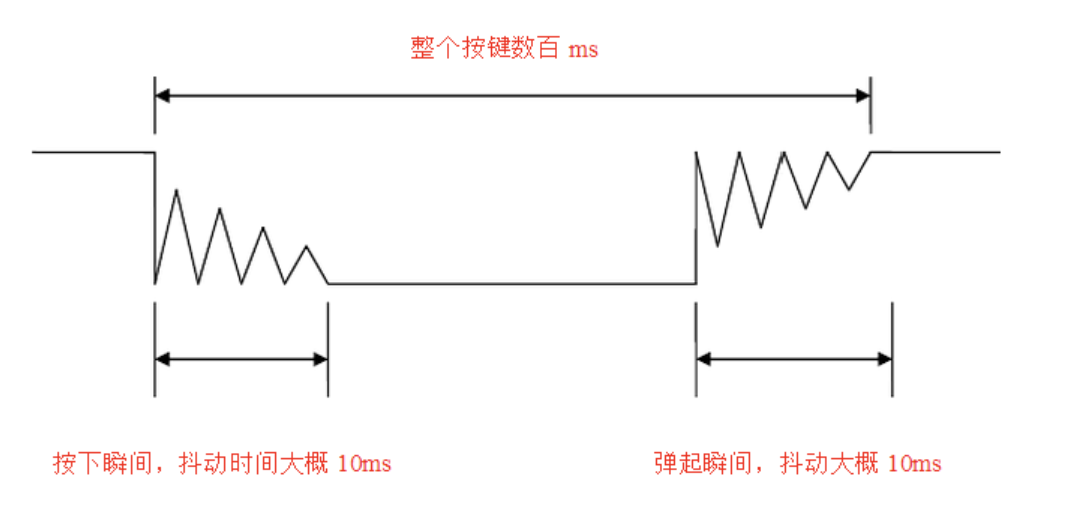
这里以(下降沿触发)为例。解决方案为:检测到第一次下降沿后,先延时>10ms,再检测按键是否仍然处于低电平,如果是说明确实是被按下了,如果不是可能只是一个小抖动。
module debounce (clk,key,rst,key_pulse);
	input key;
	input rst;
	input clk;
	output key_pulse;

	reg key_rst_pre;
	reg key_rst;


	reg [17:0] cnt;

	wire key_edge;

	always @(posedge clk or negedge rst)
		begin
			if(!rst) begin
				key_rst_pre<=1'b1;
				key_rst<=1'b1;
			end
			else begin
				key_rst<=key;
				key_rst_pre<=key_rst;
			end
		end

	assign key_edge=key_rst_pre&~(key_rst);
	reg key_sec_pre,key_sec;

	always @(posedge clk or negedge rst)
		begin
			if(!rst)
				cnt<=18'h0;
			else if(key_edge)
				cnt<=18'b0;
			else
				cnt<=cnt+1'h1;
		end

	always @(posedge clk or negedge rst)
		begin
			if(!rst)
				key_sec<=1'b1;
			else if(cnt==18'h3ffff)
				key_sec<=key;
		end

	always @(posedge clk or negedge rst)
		begin
			if(!rst)
				key_sec_pre<=1'b1;
			else
				key_sec_pre<=key_sec;
		end

	assign key_pulse=key_sec_pre&~(key_sec);

endmodule
下降沿的时候 key_edge 置1,只有当起始状态上升沿, key_edge 下降后一定时间内没有新的下降沿(无抖动)且此时仍然为下降沿时脉冲信息才为1.
处理脉冲部分很简单,读到 pulse 如果是1就翻转 led,否则保持。
module top (clk,key,led,rst);

	input clk;
	input key;
	input rst;
	output reg led;

	wire key_pulse;

	debounce u1 (
		.clk(clk),
		.key(key),
		.rst(rst),
		.key_pulse(key_pulse)
	);

	always @ (posedge clk or negedge rst)
		begin
			if(!rst)
				led<=1'b1;
			else if(key_pulse)
				led<=~led;
			else
				led<=led;
		end

endmodule
这里写的时候有一个很有趣的bug,我把cnt计数++部分漏掉了,然后生成引脚图定义的时候 clk key rst 都是 unconnected 的引脚,查了一下说是“编译器认为你这几个输入对输出无影响 就自动忽略了”。
计时控制
需求:写一个篮球24s计时软件。要求:
- 上电后从24开始倒计时到0为止停止。
- 按下 rst 归位到24.
- 按下按钮后暂停当前计时,再次按下后继续计时。
主要就是写一个模块用到了时钟分频模块(传入参数设定间隔1s),按键模块(用刚刚用的消抖的)。数码管显示 LED显示都可以在本模块内补全。
写的时候发现一个 always 赋值语法规范:一个变量赋值不要在多个 always 里分别有过赋值,会报错,尽量集中到一个 always 里。
module BasketballBoard (key, clk, rst, seg_led_1,seg_led_2,led);
	input key, clk, rst;
	output [8:0] seg_led_1;
	output [8:0] seg_led_2;
	output reg [7:0] led;

	reg [8:0] seg [9:0];

	reg [4:0] SED_LED_H;
	reg [4:0] SED_LED_L;
	wire key_pulse;
	wire clk1h;

	reg stop_flag=0;
	reg rst_flag=0;

	initial
	begin
		seg[0]=9'h3f;
		seg[1]=9'h06;
		seg[2]=9'h5b;
		seg[3]=9'h4f;
		seg[4]=9'h66;
		seg[5]=9'h6d;
		seg[6]=9'h7d;
		seg[7]=9'h07;
		seg[8]=9'h7f;
		seg[9]=9'h6f;
	end

	always @ (posedge key_pulse)
		if(rst)
			rst_flag<=~rst_flag;


	debounce u1 (
			.clk(clk),
			.rst(rst),
			.key(key),
			.key_pulse(key_pulse)
		);


	div #(.WIDTH(32),.N(12000000)) u2 (
		.clk_in(clk),
		.rst_n(rst),
		.clk_out(clk1h)
		);

	always @ (posedge clk1h or negedge rst)
		begin
			if(!rst)
				begin
					SED_LED_H<=4'd2;
					SED_LED_L<=4'd4;
					stop_flag<=0;
				end
			else if((!rst_flag)&(!stop_flag))
				begin
					led<=8'b11111111;
					if(SED_LED_L)
						SED_LED_L<=SED_LED_L-4'd1;
					else if(SED_LED_H) begin
							SED_LED_L<=4'd9;
							SED_LED_H<=SED_LED_H-4'd1;
						end
					if((!SED_LED_H)&(!SED_LED_L))
						stop_flag<=1;
				end
			else
				led<=8'b00000000;
		end

	assign seg_led_1=seg[SED_LED_H];
	assign seg_led_2=seg[SED_LED_L];

endmodule
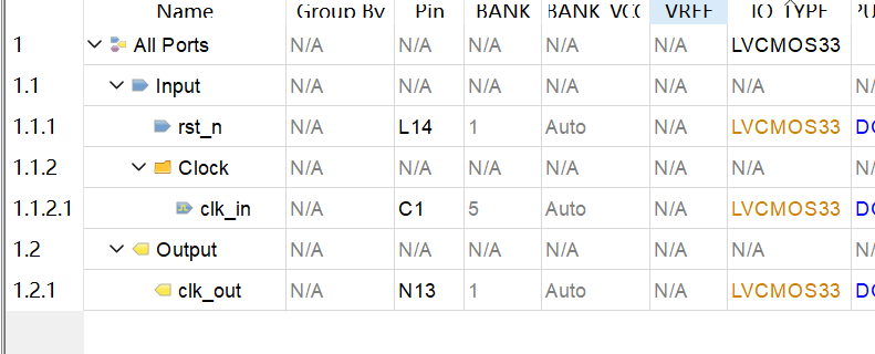
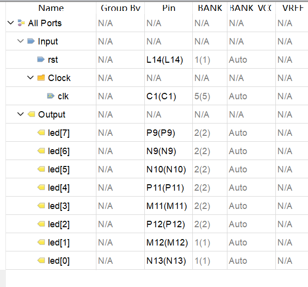
led seg key rst clk 这些都是和前面采取类似的引脚设置。再加上前面的 div 模块和 key 模块即可。
呈现效果:计时结束和按下暂停键时 LED 灯会全亮来代表暂停时钟。
LED 流水灯
PWM 原理。随着时间推移改变占空比来呈现出不同亮度的 LED。
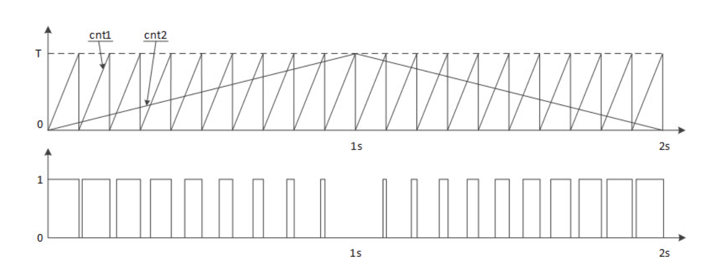
比如每个周期长度 100,第一个周期设定高电平0 低电平100,第二个周期设定高电平10 低电平90,第三个周期设定高电平20 低电平80……
也就是说我们需要两个计时器,第一个就是老老实实的记录一个又一个周期,0~Period-1.
第二个计时器一方面,在第一个计时器结束一个周期的时候改变一下自己的占空比,比如上例每个周期结束高电平部分+10.
另一方面,第二个计时器和第一个计时器作比较。比如当前第二个计时器是20也就是20高电平 80低电平,那么计时器1<计时器2的时候设置为高电平,计时器1>计时器2的时候设置为低电平。
module WaterLED(clk,rst,led);
	input clk, rst;
	output led;
	reg [13:0] cnt1;
	reg [13:0] cnt2;

	parameter CNT_NUM=2400;
	reg flag=0;

	always @ (posedge clk or negedge rst)
		begin
			if(!rst)
				cnt1<=13'b0;
			else if(cnt1==CNT_NUM-1) begin
					cnt1<=13'b0;
					if(flag==0)
						if(cnt2>=CNT_NUM) begin
								flag<=1'b1;
							end
						else cnt2<=cnt2+13'b1;
					else if(flag==1)
						if(cnt2<=0) begin
								flag<=1'b0;
							end
						else cnt2<=cnt2-13'b1;
				end
			else cnt1<=cnt1+13'b1;
		end


	assign led=cnt1<cnt2?1:0;
endmodule
代码没啥难的。
交通信号灯
两个三色模块各亮各的,表示主路和支路的红绿灯信号。
主路:15绿,3黄,10红(单位:秒)。
支路:7绿,3黄,18红。
概念:状态机,一种抽象模型。对象有状态(state,比如此例中两个红绿灯的三种状态),事件(event,外界施加的,比如我让计数–,或者切换状态颜色),行为(action,交通灯按 event 自己执行的动作,比如切颜色),切换状态(transition,比如红灯绿灯黄灯之间三种状态)。
一开始觉得很容易写。就是两个数组存储主路支路状态表嘛。
module TrafficLED (clk,rst,LED_1,LED_2);
	input clk,rst;
	output reg [2:0] LED_1;
	output reg [2:0] LED_2;

	reg [4:0] state_1 [2:0];
	reg [4:0] state_2 [2:0];
	reg [2:0] color_state [2:0];

	reg [2:0] cur_state_1;
	reg [2:0] cur_state_2;
	reg [4:0] cur_time_1;
	reg	[4:0] cur_time_2;

	wire clk1h;

	initial begin
		state_1[0]=5'd14;
		state_1[1]=5'd2;
		state_1[2]=5'd9;
		state_2[0]=5'd6;
		state_2[1]=5'd2;
		state_2[2]=5'd17;
		color_state[0]=3'b101;
		color_state[1]=3'b100;
		color_state[2]=3'b110;
		cur_time_1=5'd14;
		cur_time_2=5'd6;
	end

	div #(.WIDTH(32),.N(12000000)) u2 (
        .clk_in(clk),
        .rst_n(rst),
        .clk_out(clk1h)
    );

	always @ (posedge clk1h or negedge rst) begin
			if(!rst) begin
					cur_state_1<=0;
					cur_state_2<=0;
					cur_time_1<=5'd14;
					cur_time_2<=5'd6;
					LED_1<=color_state[cur_state_1];
					LED_2<=color_state[cur_state_2];
				end
			else begin
					if(cur_time_1)cur_time_1<=cur_time_1-5'b1;
					else begin
							if(cur_state_1<2)cur_state_1<=(cur_state_1+1);
							else cur_state_1<=0;
							cur_time_1<=state_1[cur_state_1+1];
						end
					if(cur_time_2)cur_time_2<=cur_time_2-5'b1;
					else begin
							if(cur_state_2<2)cur_state_2<=(cur_state_2+1);
							else cur_state_2<=0;
							cur_time_2<=state_2[cur_state_2+1];

						end
					LED_1<=color_state[cur_state_1];
					LED_2<=color_state[cur_state_2];
				end
		end

endmodule
有两个注意的地方,都是和 fpga 非阻塞赋值相关的。
之前知道 always 里如果用 <= 赋值,所有变量是结束 always 的时候同时赋值的。第一个错误写法是这么写的:
if(cur_time_1)cur_time_1<=cur_time_1-5'b1;
else begin
        if(cur_state_1<2)cur_state_1<=(cur_state_1+1);
        else cur_state_1<=0;
    	cur_time_1<=state_1[cur_state_1];//这里有区别
    end
if(cur_time_2)cur_time_2<=cur_time_2-5'b1;
else begin
        if(cur_state_2<2)cur_state_2<=(cur_state_2+1);
        else cur_state_2<=0;
    	cur_time_2<=state_2[cur_state_2];//这里有区别
    end
LED_1<=color_state[cur_state_1];
LED_2<=color_state[cur_state_2];
因为我想的是,cur_state+1后切换状态为当前cur_state的状态,也就是已经+1过后的状态。
实际不是这么回事,实际上他俩指令是同时执行的,也就是说state[cur_state]还是刚才没+1的状态。
所以我改成 state[cur_state+1] 了。
第二个错误如下:
if(cur_time_1)cur_time_1<=cur_time_1-5'b1;
else begin
        cur_state_1<=(cur_state_1+1);//这里有区别
    	if(cur_state_1==3)cur_state_1<=0;//这里有区别
    	cur_time_1<=state_1[cur_state_1+1];
    end
if(cur_time_2)cur_time_2<=cur_time_2-5'b1;
else begin
    	cur_state_2<=(cur_state_2+1);//这里有区别
    	if(cur_state_2==3)cur_state_2<=0;//这里有区别
    	cur_time_2<=state_2[cur_state_2+1];
    end
LED_1<=color_state[cur_state_1];
LED_2<=color_state[cur_state_2];
想的也是顺序执行,先+1判断是否超出了(0,1,2)的数组范围,如果超出了就归0.
但是 LED 赋值和 cur_state+1 是同时执行的,也就是有1s我的cur_state是3,LED也尝试获取数组3下标的状态。
所以干脆赋值的时候就:如果为2,直接归0,否则++。这样就不用再一步判断了。